Indicators, Other parts, Connectors – JVC 0597TOV*UN*VP User Manual
Page 51
51
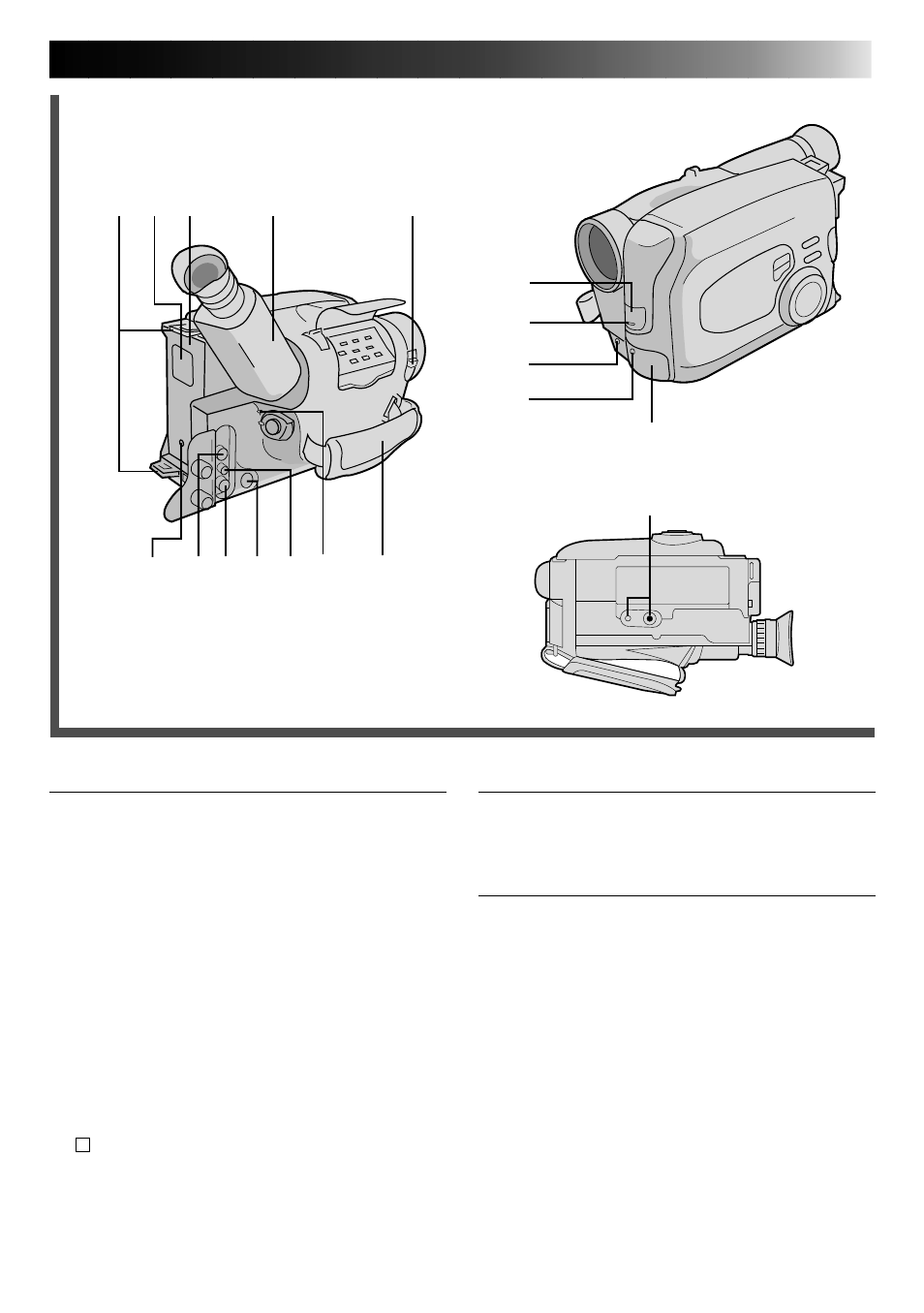
Indicators
Q
Tally Lamp .........................................
੬
pg. 14
W
Power On Indicator ...........................
੬
pg. 14
Other Parts
E
• Camera sensor
Be careful not to cover this area; built-in
here is the sensor necessary for shooting.
• Remote sensor .................................
੬
pg. 43
R
Microphone .......................................
੬
pg. 45
T
Shoulder Strap Eyelets ........................
੬
pg. 13
Y
Clock Battery Compartment ................
੬
pg. 8
U
Battery Pack Mount ...........................
੬
pg. 6
I
Electronic Viewfinder .........................
੬
pg. 8
O
LENS COVER Switch .........................
੬
pg. 14
P
Grip Strap ..........................................
੬
pg. 12
a
Tripod Mounting Socket ......................
੬
pg. 13
y
i
p
o
u
W
Y
T
U
I
O
P
r
t
E
R
Q
a
Connectors
r
J terminal (JLIP (Joint Level Interface Protocol)
Connector.)
(Located beneath the jack cover)
• Connect the Editing Cable when performing
Random Assemble Editing (
੬
pg. 39).
•It is used to connect the camcorder to a device
such as a personal computer.
For further detail consult your nearest JVC
dealer. Information (in English) is also available
at our home page: http://www.jvc-victor.co.jp/
t
External MIC Jack (capped) .................
੬
pg. 45
y
DC IN Jack .........................................
੬
pg. 7
The jacks
u
to
p
are located beneath the jack
cover.
u
AUDIO OUT Jack ..............................
੬
pg. 32
i
VIDEO OUT Jack ...............................
੬
pg. 32
o
S
-VIDEO OUT Jack ..........................
੬
pg. 32
p
RF DC OUT Jack ................................
੬
pg. 33