Installation and setup, Wiring, Actuator wiring options – Jade Range W7220 User Manual
Page 2: Warning, Caution
JADE
™
ECONOMIZER MODULE
62-0331—11
2
INSTALLATION AND SETUP
The Economizer module may be mounted in any orientation.
However, mounting in the orientation shown above permits
proper viewing of the LCD display and use of the keypad.
NOTE: Jade will be in the “set up” mode for the first 60
minutes after powered. If a sensor for OA air or
Sylkbus device (sensor, actuator) is discon-
nected during the set up mode, the Jade will not
alarm that failure. The MA sensor is a system
“critical” sensor; if the MA sensor is removed
during the set up mode, the Jade will alarm. After
60 minutes the Jade controller will change to
operation mode and all components removed or
failed will alarm in the operation mode.
WIRING
All wiring must comply with applicable electrical codes and
ordinances, or as specified on installation wiring diagrams.
Module wiring in the field is terminated to the four screw
terminal blocks located on the left and right sides.
Module wiring at the OEM factory is terminated via the header
pin terminals located on the left and right sides. The header
terminal pins and the terminal blocks have common
terminations for the appropriate input or output. The part
number for the OEM female mating connector is 0039973997.
WARNING
Electrical Shock Hazard.
Can cause severe injury, death or property
damage.
Disconnect power supply before beginning wiring, or
making wiring connections, to prevent electrical shock
or equipment damage.
CAUTION
Equipment Damage Hazard.
Electrostatic discharge can short equipment
circuitry.
Ensure that you are properly grounded before
handling the unit.
Each terminal can accommodate the following gauges of wire:
• Single wire – from 18 AWG to 22 AWG solid or stranded
• Multiple wires – up to two 22 AWG stranded
• For the 24 Vac connections: single wire – from 14 to 18
AWG solid or stranded
For S-BUS wiring, the sensors may be mounted up to 200 ft.
(61 m) from the JADE controller. When the length of wire is
over 100 feet use twisted pair shielded wire.
NOTE: All wiring is polarity insensitive.
Refer to Fig. 1 through Fig. 6 for common wiring
configurations.
Actuator Wiring Options:
1. The JADE economizer controller can only have one (1)
communicating actuator connected to it.
2. Up to four (4) non-communicating and (2) 2-position
actuators (1 each on EXH1 and AUX1 O)
3. One (1) communicating and up to four (4) non-commu-
nicating and (2) 2-position actuators (1 each on EXH1
and AUX1 O)
When using a 2-position actuator on the AUX1 O the AUX1 O
must be programmed for Exh2 and the % open is the % open
of the outdoor damper when the 2-pos actuator opens.
Connect 24 V to Exh1 and/or AUX1 O and ground to the Jade
“C” terminal.
Note the W7220 economizer will not work with an old “black
motor” M7415; replace the M7415 with a M7215 or MS3103
DCA.
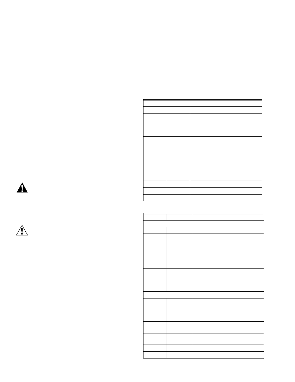
Table 1. Economizer Module - Left hand terminal blocks.
Label
Type
Description
Top Left Terminal Block
MAT
MAT
20k NTC
and COM
Mixed Air Temperature Sensor
(polarity insensitive connection)
OAT
OAT
20k NTC
and COM
Outdoor Air Temperature Sensor
(polarity insensitive connection)
S-BUS
S-BUS
SYLK Bus Sylk Bus sensor
(polarity insensitive connection)
Bottom Left Terminal Block
IAQ 2-10
2-10 Vdc
Air Quality Sensor Input
(e.g. CO
2
sensor)
IAQ COM COM
Air Quality Sensor Common
IAQ 24V
24 Vac
Air Quality Sensor 24 Vac Source
ACT 2-10
2-10 Vdc
Damper Actuator Output (2-10 Vdc)
ACT COM COM
Damper Actuator Output Common
ACT 24V
24 Vac
Damper Actuator 24 Vac Source
Table 2. Economizer Module - Right hand terminal blocks.
Label
Type
Description
Top Right Terminal Block
n/a
The first terminal is not used
AUX2 I
24 Vac IN
Shut Down (SD) or Heat (W)
Conventional only or
Heat Pump Changeover (O/B) in
Heat Pump mode.
OCC
24 Vac IN
Occupied / Unoccupied Input
E-GND
EGND
Earth Ground - System Required
EXH1
24 Vac OUT Exhaust Fan 1 Output
AUX1 O
24 Vac OUT Programmable:
Exhaust fan 2 output or
ERV or System Alarm output.
Bottom Right Terminal Block
Y2-I
24 Vac IN
Y2 in - Cooling Stage 2 Input from
space thermostat
Y2-O
24 Vac OUT Y2 out - Cooling Stage 2 Output to
stage 2 mechanical cooling
Y1-I
24 Vac IN
Y1 in - Cooling Stage 1 Input from
space thermostat
Y1-O
24 Vac OUT Y1 out - Cooling Stage 1 Output to
stage 1 mechanical cooling
C
COM
24 Vac Common
R
24 Vac
24 Vac Power (Hot)