Troubleshooting, Alarms – Jade Range W7220 User Manual
Page 19
JADE
™
ECONOMIZER MODULE
19
62-0331—11
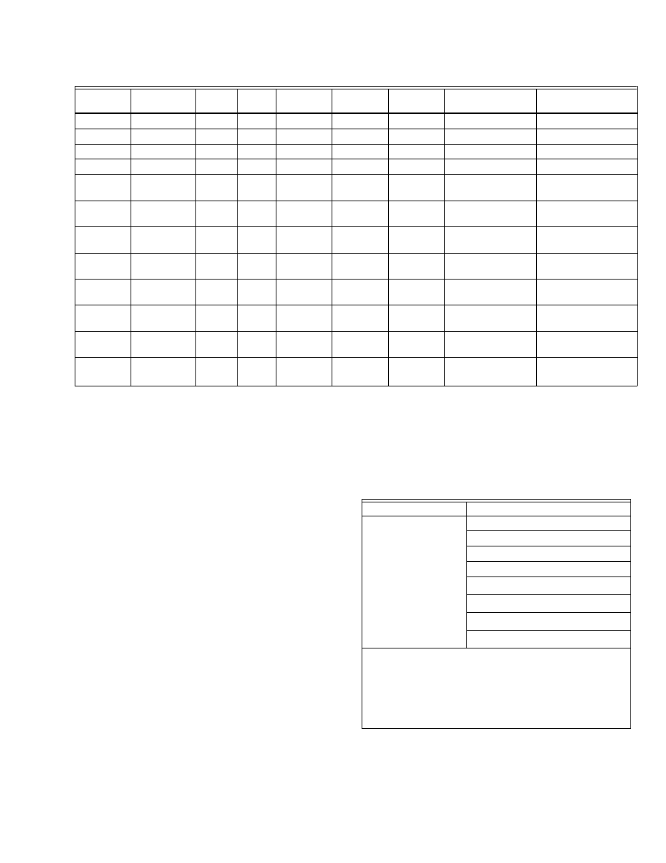
Table 12. Enthalpy Operation With DCV (CO2 sensor) - 2 Speed Fan.
a
With stage 3 delay (STG3 DLY) in Advanced setup menu can turn on 2nd stage of mechanical cooling Y2 –O after the delay if
the call for Y1-I and Y2-I have not been satisfied.
b
With 2SP FAN DELAY (Advanced Setup Menu) when in the economizing mode there is a delay for the high speed fan to try to
satisfy the call for second stage cooling by turning on the fan to high and opening the OA damper 100% before the first stage
mechanical cooling is enabled.
TROUBLESHOOTING
Alarms
The Economizer module provides alarm messages that
display on the 2-line LCD.
NOTE: Upon power up, the module waits 60 minutes
before checking for alarms. This allows time for
all the configured devices (e.g. sensors, actua-
tor) to become operational. The exception is the
MA sensor which will alarm immediately. If one or
more alarms are present and there has been no
keypad activity for at least 5 minutes, the Alarms
menu displays and cycles through the active
alarms.
You can also navigate to the Alarms menu at any time.
DCV
OA Good to
economize?
Y1-I
Y2-I
FAN SPD
Y1-O
Y2-O
Occupied
Unoccupied
Below set
No
Off
Off
Low
0-v/Off
0-v/Off
VENTMIN L
Closed
On
Off
Low
24-v/On
0-v/Off
VENTMIN L
Closed
On
On
High
24-v/On
24-v/On
VENTMIN H
Closed
Yes
Off
Off
Low
0-v/Off
0-v/Off
VENTMIN L
Closed
On
Off
Low
0-v/Off
0-v/Off
VENTMIN L to Full-
Open
Closed to Full-Open
On
On
High
24-v/On
0-v/Off
a
VENTMIN H to Full-
Open
Closed to Full-Open
Above set
No
Off
Off
Low
0-v/Off
0-v/Off
VENTMIN L to
VENTMAX
Closed
On
Off
Low
24-v/On
0-v/Off
VENTMIN L to
VENTMAX
Closed
On
On
High
24-v/On
24-v/On
VENTMIN H to
VENTMAX
Closed
Yes
Off
Off
Low
0-v/Off
0-v/Off
VENTMIN L to
VENTMAX
Closed
On
Off
Low
0-v/Off
0-v/Off
VENTMIN L to Full-
Open
Closed to Full-Open
On
On
High
DELAY
b
24-v/On
0-v/Off
a
VENTMIN H to Full-
Open
Closed to Full-Open
Table 13. Alarms Menu.
Menu
Alarm
ALARMS(_)
MA T SENS ERR
CO2 SENS ERR
OA T SENS ERR
DA ENTHL ERR
SYS ALARM
a
a
When AUX1 O is set to SYS and there is any alarm (e.g.,
failed sensors, etc.), the AUX1 O terminal has 24 Vac out
and the LCD displays the ALARM.
b
This alarm is only displayed when a communicating actuator
is used. (ex: MS3105AJ)
ACT Over Voltage
b
ACT Under Voltage
b
ACT Stalled
b
NOTES:
1.
The Alarms menu displays only when alarm(s)
are active and includes the number of active
alarms in parenthesis ().
2.
The alarms listed are a few examples. Additional
alarms display depending on the parameter set-
tings and configuration.