Jade Range W7220 User Manual
Page 15
JADE
™
ECONOMIZER MODULE
15
62-0331—11
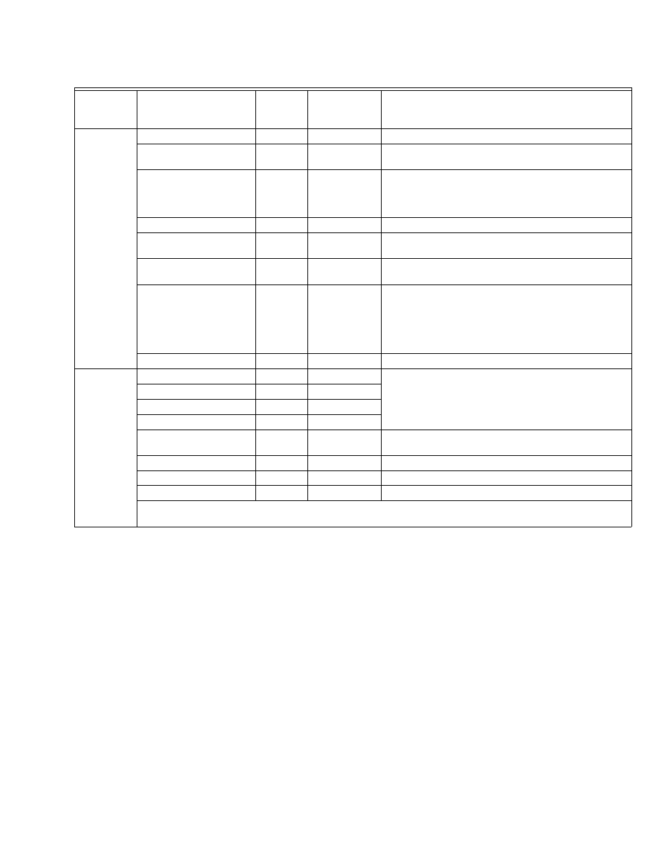
CHECKOUT
f
DAMPER VMIN-HS
n/a
n/a
Positions damper to VMIN position.
DAMPER VMAX-HS (LS) n/a
n/a
Positions damper to VMAX position. With 2-speed fan units the
damper will position to VMAX low speed fan.
DAMPER OPEN
n/a
n/a
Positions damper to the full open position.
Exhaust fan contacts enable during the DAMPER OPEN test.
Make sure you pause in this mode to allow for exhaust contacts
to energize due to the delay in the system.
DAMPER CLOSE
n/a
n/a
Positions damper to the fully closed position.
CONNECT Y1-O
n/a
n/a
Closes the Y1-O relay (Y1-O).
See CAUTION on page 20
CONNECT Y2-O
n/a
n/a
Closes the Y2-O relay (Y2-O).
See CAUTION on page 20
CONNECT AUX1-O
n/a
n/a
Energizes the AUX1-O output. If AUX1-O setting is:
• NONE – no action taken
• ERV – 24 Vac out. Turns on or signals an ERV that the
conditions are not good for economizing but are good for
ERV operation.
d
• SYS – 24 Vac out. Issues a system alarm.
CONNECT EXH1
n/a
n/a
Closes the power exhaust fan 1 relay (EXH1)
ALARMS(_) MA T SENS ERR
n/a
n/a
Alarms display only when they are active. The menu title
“ALARMS (_)” includes the number of active alarms in
parenthesis ().
CO2 SENS ERR
n/a
n/a
OA T SENS ERR
n/a
n/a
DA ENTHL ERR
n/a
n/a
SYS ALARM
n/a
n/a
When AUX1-O is set to SYS and there is any alarm (e.g., failed
sensors, etc.), the AUX1-O terminal has 24 Vac out.
ACT UNDER V
n/a
n/a
Voltage received by Actuator is above expected range
ACT OVER V
n/a
n/a
Voltage received by Actuator is below expected range
ACT STALLED
n/a
n/a
Actuator stopped before achieving commanded position
NOTE: The alarms listed are examples. Additional alarms display depending on the parameter settings
and configuration.
a
Table 4 illustrates the complete hierarchy. Your menu parameters may be different depending on your configuration.
For example if you do not have a DCV (CO
2
) sensor, then none of the DCV parameters appear.
b
When values are displayed, pressing and holding the
or
button causes the display to automatically increment.
c
n/a = not applicable
d
ERV Operation: When in Cooling mode AND the conditions are NOT OK for economizing - the ERV terminal will be energized. In
the Heating mode the ERV terminal will be energized when the OA is below the ERV OAT setpoint in the setpoint menu.
e
When used with Honeywell communicating actuator the damper out is reported in XX.X% open versus XX.X Vdc.
f
After 10 minutes without a command or mode change, the controller will change to normal operation.
Table 4. Menu Structure
a
. (Continued)
Menu
Parameter
Parameter
Default
Value
Parameter
Range and
Increment
b
Notes