Blade parallel to the miter slot, Additional blade adjustments – Jet Tools JOB SITE TABLE SAW JBTS-10MJS User Manual
Page 20
20
Blade Parallel to the Miter Slot
To avoid injury from an
accidental start, make sure the switch is in the
OFF position and the plug is disconnected from
the power source outlet.
This adjustment was made at the factory, but it
should be rechecked and adjusted if necessary.
This adjustment must be correct to assure accurate
cuts and to prevent the possibility of kickback,
which can result in serious injury.
Referring to Figure 22:
1. Remove the yellow switch key and unplug the saw.
2. Remove the blade guard.
3. Raise the blade to the maximum height and set
the bevel angle at 0°
4. Select and mark with a felt tip marker, one
blade tooth with a “right set” angle and position
this tooth at the front of the saw approximately
1/2 in. above the table (D) .
Figure 22
5. Place the combination square base (G) into the
right side miter gauge slot (F) flush against the
inside of the miter gauge slot.
6. Adjust the ruler (E) so it touches the front
marked tooth (D) and lock ruler so it holds its
position in the square assembly.
7. Next rotate the blade, moving the marked tooth
(D) to its new position (A) at the rear of the
saw.
8. Carefully move the combination square from
position (G) to (C).
9. If the ruler touches the marked tooth at the
front and rear position (E at D, B at A), no
adjustment is needed. If not, perform the
adjustment procedure described in the next
section.
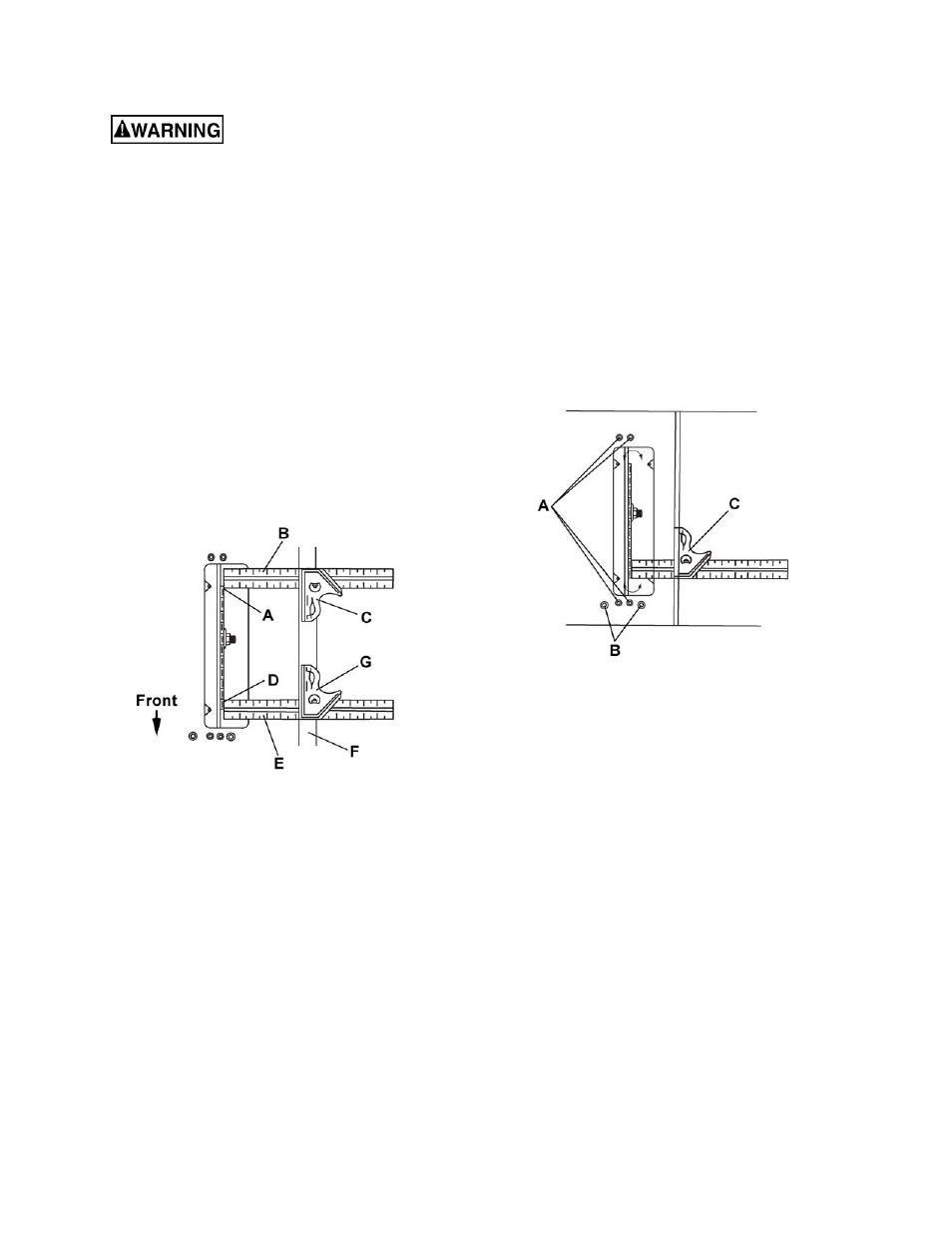
Additional Blade Adjustments
Refer to Figure 23.
If the front and rear measurements are not the
same:
1. Remove the combination square (C) and
loosen the four adjusting screws (A) on the top
of the table about a half turn.
2. Cover the blade with a folded piece of
cardboard to protect your hands. Move the
blade and motor mounting rod carefully to the
left or right as much as needed to align the
blade correctly.
3. Tighten the four screws (A) and remeasure, as
described in steps 4 to 9 in the previous section.
Figure 23
4. If sufficient adjustment cannot be made by the
four adjusting screws (A), then also loosen the
two adjusting screws (B) and repeat all
previous steps. Loosen these screws (B) only if
necessary as they are set for accurate 90° and
45° settings.
5. Recheck the blade clearance making sure that
the blade does not hit the table insert or other
parts when at the 90° and 45° settings.
6. Retighten all four adjusting screws (A) and
reset the 90° and 45° setting as described in
the 90° and 45° Positive Stop Adjustment
section (page 19).