Blade guard assembly – Jet Tools JOB SITE TABLE SAW JBTS-10MJS User Manual
Page 15
15
Blade Guard Assembly
To avoid injury from an
accidental start, make sure the switch is in the
OFF position and the plug is disconnected from
the power source outlet.
● When installing the blade guard, cover the
blade teeth with a piece of folded cardboard to
protect yourself from possible injury.
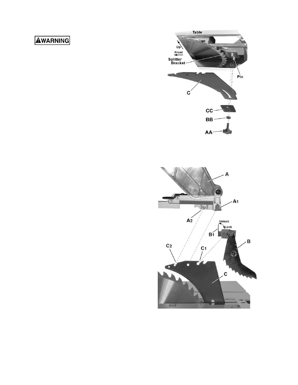
Splitter (riving knife) installation (Figure 12)
1. Remove the table insert.
2. Raise the blade arbor to the maximum height
and set the bevel angle to 0°.
3. Install
the
splitter (C) onto the splitter bracket,
fitting the curved slot on the splitter over the
bracket pins.
4. Install the splitter plate (CC), followed by the
flat washer (BB) and lock knob (AA). Tighten
the lock knob, leaving enough slack to
manually adjust the splitter (C).
5. Raise
the
splitter (C) as high as it will go, then
tighten the lock knob (AA) to secure the splitter
in this position.
Kickback pawl installation (Figure 12a)
6. Place
the
lock lever (B
1
) on the kickback pawl
assembly (B) in the unlock position.
7. Install the kickback pawl (B) onto the splitter.
The flat sides of the mounting pin on the
kickback pawls
should pass though the
mounting slot (C1) on the splitter (C).
Note: Make sure the “anti-kick back pawls do
not get caught between the insert and the
guard, but rest on top of the insert.
8. Press firmly down on the kickback pawl to
ensure that it is properly seated on the splitter,
then place the lock lever (B1) in the lock
position.
Blade guard installation (Figure 12a)
9. Slide
the
lock lever (A1) on the blade guard (A) up
and hold..
10. Place the blade guard (A) on the splitter (C),
meshing the pin (A
2
) on the blade guard with the
slot (C
2
) on the splitter.
11. Push the blade guard assembly down firmly on the
splitter; then release the lock lever (A
1
).
12. Lift up on the blade guard assembly (A) to confirm
that it is firmly secured to the splitter (C).
Figure 12
Figure 12a