2 uart, Figure 20. uart connection to peripheral bus, Table 89. uart register settings – Intel IQ80219 User Manual
Page 73: 3 rotary switch, Uart, Rotary switch, Uart connection to peripheral bus, Uart register settings
73
Intel® IQ80219 General Purpose PCI Processor Evaluation Platform
Software Reference
5.2.2
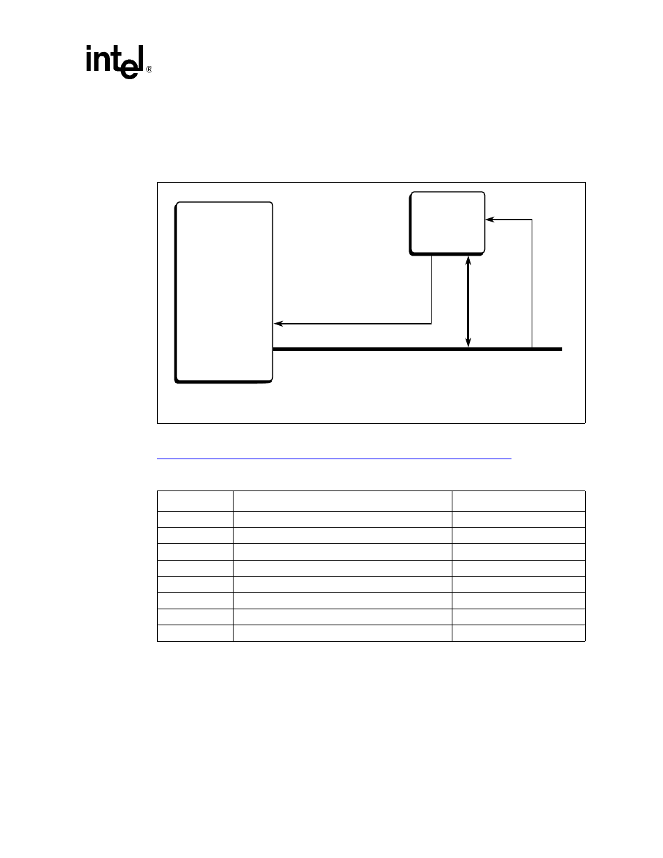
UART
The UART is a TL16C550C. It sits on the Peripheral Bus and is accessed using PCE1 and XINT1# as
shown in
See datasheet at the following link for more information and a pin layout of this device:
5.2.3
Rotary Switch
The Rotary switch changes the value of a memory mapped register so it can be read later from
software. For example, it can be used to allow the user to select from various boot-up flavors. The
Rotary Switch is accessed using Peripheral Chip Enable #4 (PCE4) through PC_AD[0:3].
Figure 20.
UART Connection to Peripheral Bus
B2832-01
Texas
Instruments*
TL16C550C
UART0
CS
XINT2#
PCE1
INTERRUPT
Intel
®
80219
General Purpose
PCI Processor
* Other names and brands may be claimed as property of others.
Intel
®
80219 General Purpose PCI
Processor Peripheral Bus
Table 89.
UART Register Settings
Address
Read Register
Write Register
FE81 0000H
Receive Holding Register
Transmit Holding Register
FE81 0001H
Unused
Interrupt Enable Register
FE81 0002H
Interrupt Status Register
FIFO Control Register
FE81 0003H
Unused
Line Control Register
FE81 0004H
Unused
Modem Control Register
FE81 0005H
Line Status Register
Unused
FE81 0006H
Modem Status Register
Unused
FE81 0007H
Scratchpad Register
Scratchpad Register