5 mictor j3f2, Table 18. micor j3f2 signal/pins, Mictor j3f2 – Intel IQ80219 User Manual
Page 46: Micor j3f2 signal/pins
46
Intel® IQ80219 General Purpose PCI Processor Evaluation Platform
Hardware Reference Section
3.8.5
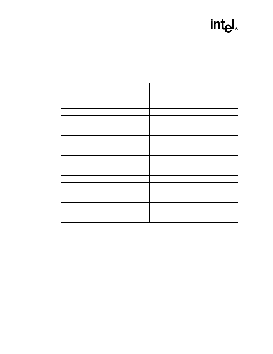
Mictor J3F2
Warning:
Be sure to fully understand the pin assignments of the particular logic analyzer being used before
connecting to the Intel
®
IQ80219 evaluation platform board. When voltage is applied, particularly
to a NC pin, hardware damage can be incurred.
Table 18.
Micor J3F2 Signal/Pins
Schematic Signal Name
Mictor Pin
Name
Mictor Pin
Name
Schematic Signal Name
FLASH_SEL/RST_MODE*
1
2
PB_AD<13>
ROT_SW_SEL*
3
4
PB_AD<14>
MSB_LED_DEL*
5
6
PB_AD<15>
LSB_LED_SEL*
7
8
PB_AD<16>
UART_SEL/RETRY*
9
10
PB_AD<17>
FLASH_SEL/RST_MODE*
11
12
PB_AD<18>
PB_AD<0>
13
14
PB_AD<19>
PB_AD<1>
15
16
PB_AD<20>
PB_AD<2>
17
18
PB_AD<21>
PB_AD<3>
19
20
PB_AD<22>
PB_AD<4>
21
22
PB_AD<23>
PB_AD<5>
23
24
PB_AD<24>
PB_AD<6>
25
26
PB_AD<25>
PB_AD<7>
27
28
PB_AD<26>
PB_AD<8>
29
30
PB_AD<27>
PB_AD<9>
31
32
PB_AD<28>
PB_AD<10>
33
34
PB_AD<29>
PB_AD<11>
35
36
PB_AD<30>
PB_AD<12>
37
38
PB_AD<31>
- 41210 (64 pages)
- 8xC251TQ (20 pages)
- ENTERPRISE PRINTING SYSTEM (EPS) 4127 (84 pages)
- U3-1L (20 pages)
- 80960HA (104 pages)
- X58 (54 pages)
- ESM-2850 2047285001R (91 pages)
- ATOM US15W (54 pages)
- D915GVWB (4 pages)
- XP-P5CM-GL (28 pages)
- AX965Q (81 pages)
- CORETM 2 DUO MOBILE 320028-001 (42 pages)
- CV700A (63 pages)
- 80C188EA (50 pages)
- X25-M (28 pages)
- XP-P5IM800GV (26 pages)
- IB868 (60 pages)
- D865GVHZ (88 pages)
- IB865 (64 pages)
- Altera P0424-ND (1 page)
- 8086-2 (30 pages)
- IXDP465 (22 pages)
- IWILL P4D (104 pages)
- GA-8I955X PRO (88 pages)
- FSB400 (PC2100) (96 pages)
- D845GLAD (4 pages)
- NAR-3041 (1 page)
- 87C196CA (136 pages)
- G52-M6734XD (74 pages)
- A96134-002 (10 pages)
- Express Routers 9000 (8 pages)
- 82540EP (45 pages)
- D865GLC (94 pages)
- IB850 (69 pages)
- MB898RF (62 pages)
- Arima LH500 (78 pages)
- V09 (33 pages)
- I/O Processor (22 pages)
- M600 (110 pages)
- SE7520JR2 (63 pages)
- SERVER BOARD S5520HCT (30 pages)
- Extensible Firmware Interface (1084 pages)
- GA-8IPXDR-E (70 pages)
- D845EBG2 (4 pages)
- AW8D (80 pages)