Impex MWM 1801 User Manual
Page 20
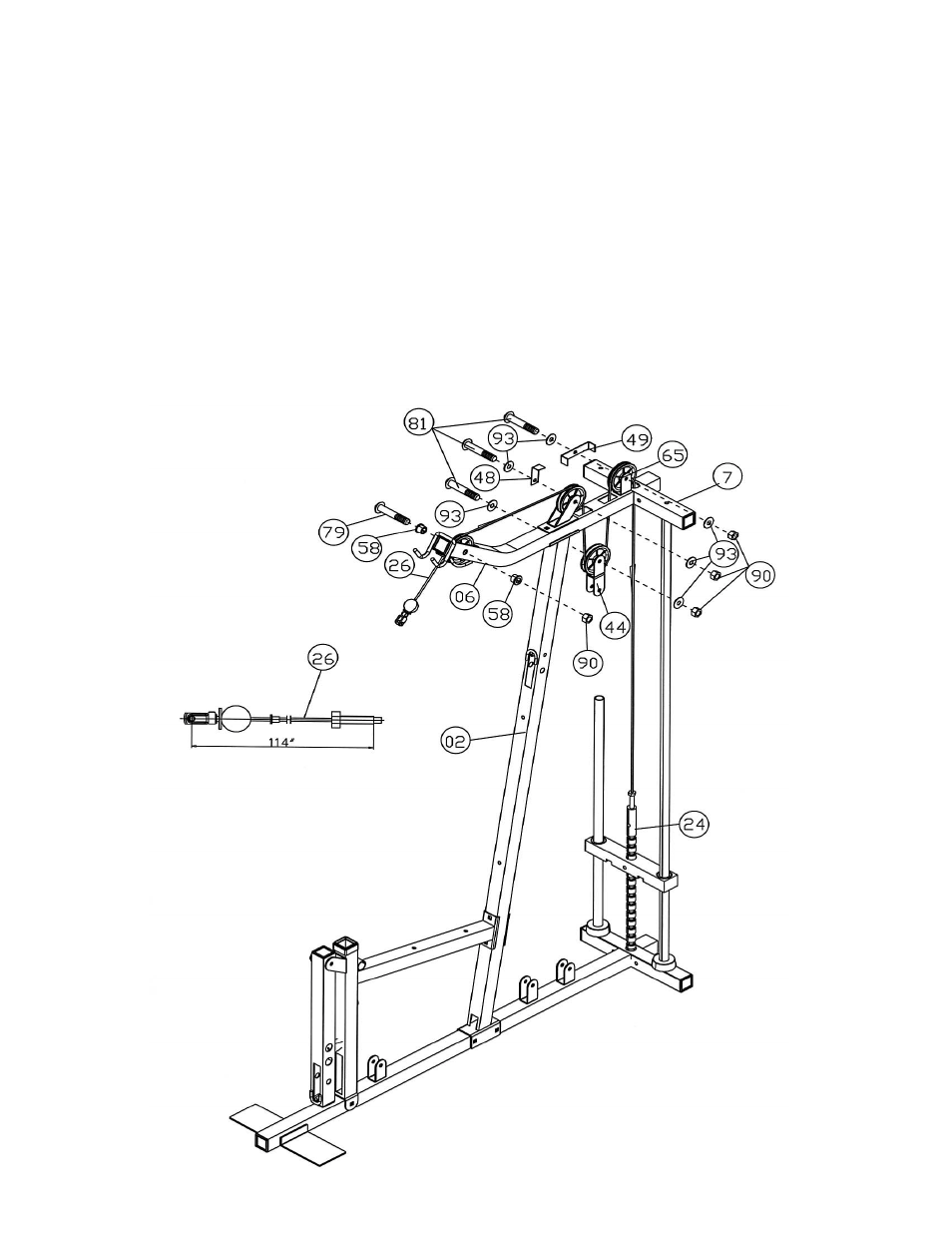
STEP 10 (See Diagram 10 & Cable Loop Diagram)
A.) Attach the 114” Upper Cable (#26) to the front opening on the Right Upper Frame (#6).
NOTE: The Ball Stopper on the Cable needs to be underneath the Frame.
B.) Attach a Pulley (#65) to the opening. Secure it with one M10 x 2 3/8” Allen Bolt (#79), two
∅
5/8” x ½” Pulley Bushings (#58), and one M10 Aircraft Nut (#90).
C.) Draw the Cable towards the back of the machine to the Pulley Bracket (#46). Install a Pulley
to the Bracket. Secure it with one M10 x 2” Allen Bolt (#81), one L-shaped Bracket (#48), two
∅
¾” Washers (#93), and one M10 Aircraft Nut (#90).
D.) Pull the Cable over the Pulley then downward. Attach a Pulley to a Double Floating Pulley
Bracket (#44). Secure it with one M10 x 2” Allen Bolt (#81), two
∅
¾” Washers (#93), and
one M10 Aircraft Nut (#90). Let the Bracket hanging for now.
E.) Pull the Cable around the Pulley then upward to the open bracket on the back of the Top
Socket Assembly (#7). Attach a Pulley to the bracket. Secure it with one M10 x 2” Allen Bolt
(#81), U-shaped Bracket (#49), two
∅
¾” Washers (#93), and one M10 Aircraft Nut (#90).
F.) Pull the Cable around the Pulley then downward to the Selector Rod (#24). Thread the bolt
at the end of the Cable into the Selector Rod.
19