Diagram 7 – Impex MWM 1801 User Manual
Page 16
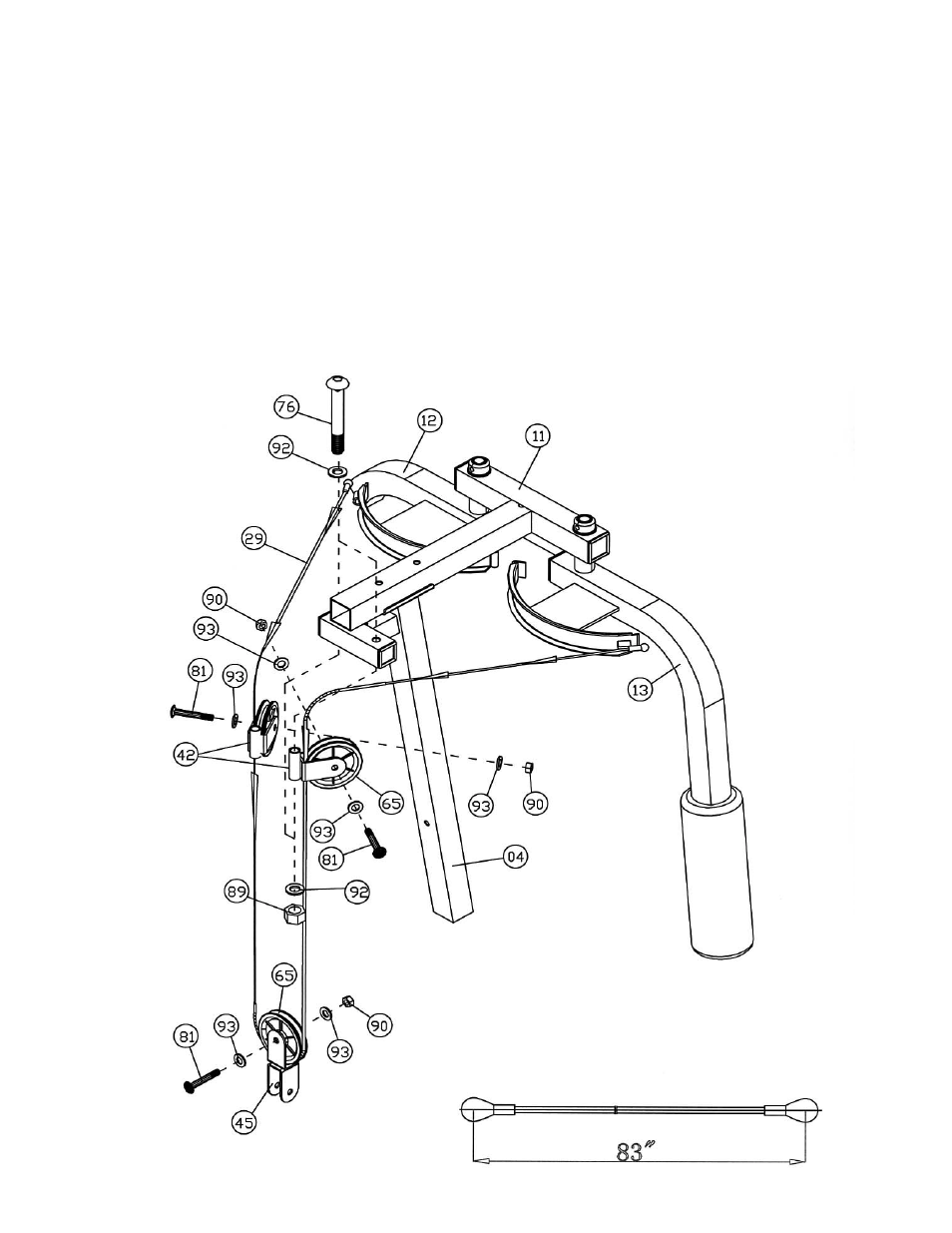
STEP 7 (See Diagram 7 & Cable Loop Diagram)
A.) Attach the two Swivel Pulley Brackets (#42) to the Left Upper Frame (#11). Secure each
Bracket with one M12 x 4 3/8” Allen Bolt (#76), two
∅
1” Washers (#92) and one M12 Aircraft
Nut (#89). NOTE: Do not over tighten the Bolt. Make sure the Bracket is able to swivel.
B.) Attach one end of the 83” Butterfly Cable (#29) to the clip on the Right Butterfly (#13). Pull
the Cable to the right open Swivel Pulley Bracket (#42).
C.) Attach a Pulley (#65) to the Bracket. Secure it with one M10 x 2 “Allen Bolt (#81), two
∅
¾”
Washers (#93), and one M10 Aircraft Nut (#90).
D.) Draw the Cable downward. Repeat Step B above to install a Pulley to the Angled Double
Pulley Bracket (#45). Let the Bracket hanging for now. Pull the Cable upward to the left
open Swivel Pulley Bracket.
E.) Repeat Step B above to install another Pulley to the Left Swivel Pulley Bracket. Draw the
Cable to the Left Butterfly (#12). Attach the end of the Cable to the clip on the Left Butterfly.
DIAGRAM 7
15