Intel MB899 User Manual
Page 18
INSTALLATIONS
14
MB899 User’s Manual
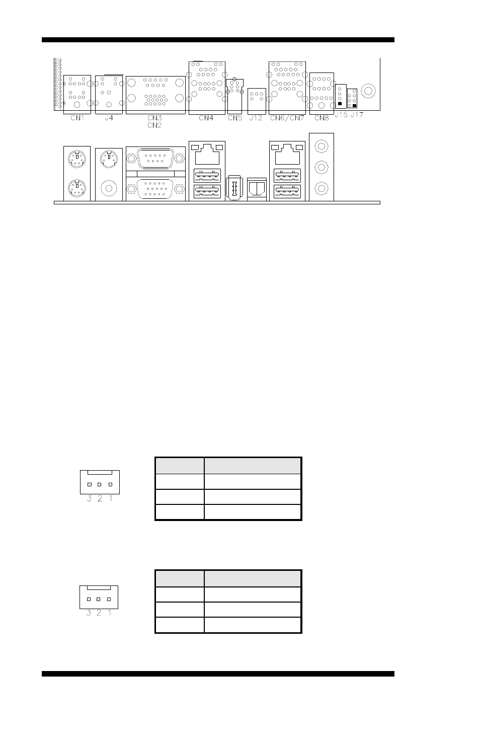
CN4: 10/100 RJ-45 and USB1/2 Ports
CN5: 1394 Connector
J12: SPDIF Out Connector
CN6: GbE RJ-45 and USB3/4 Ports
CN8: Audio Connector
The audio connector, from top to bottom, is composed of Line in, Line
out and Microphone jacks.
CN9, CN10: Serial ATA Connectors
FAN1: System Fan Power Connector
FAN1 is a 3-pin header for system fans. The fan must be a 12V (500mA).
Pin #
Signal Name
1
Ground
2
+12V
3
Rotation detection
FAN2: CPU Fan Power Connector
FAN2 is a 3-pin header for the CPU fan. The fan must be a 12V fan.
Pin #
Signal Name
1
Ground
2
+12V
3
Rotation detection
See also other documents in the category Intel Hardware:
- 41210 (64 pages)
- 8xC251TQ (20 pages)
- ENTERPRISE PRINTING SYSTEM (EPS) 4127 (84 pages)
- U3-1L (20 pages)
- 80960HA (104 pages)
- X58 (54 pages)
- ESM-2850 2047285001R (91 pages)
- ATOM US15W (54 pages)
- D915GVWB (4 pages)
- XP-P5CM-GL (28 pages)
- AX965Q (81 pages)
- CORETM 2 DUO MOBILE 320028-001 (42 pages)
- CV700A (63 pages)
- 80C188EA (50 pages)
- X25-M (28 pages)
- XP-P5IM800GV (26 pages)
- IB868 (60 pages)
- D865GVHZ (88 pages)
- IB865 (64 pages)
- Altera P0424-ND (1 page)
- 8086-2 (30 pages)
- IXDP465 (22 pages)
- IWILL P4D (104 pages)
- GA-8I955X PRO (88 pages)
- FSB400 (PC2100) (96 pages)
- D845GLAD (4 pages)
- NAR-3041 (1 page)
- 87C196CA (136 pages)
- G52-M6734XD (74 pages)
- A96134-002 (10 pages)
- Express Routers 9000 (8 pages)
- 82540EP (45 pages)
- D865GLC (94 pages)
- IB850 (69 pages)
- MB898RF (62 pages)
- Arima LH500 (78 pages)
- V09 (33 pages)
- I/O Processor (22 pages)
- M600 (110 pages)
- SE7520JR2 (63 pages)
- SERVER BOARD S5520HCT (30 pages)
- Extensible Firmware Interface (1084 pages)
- GA-8IPXDR-E (70 pages)
- D845EBG2 (4 pages)
- AW8D (80 pages)