Connecting usb 2.0 headers, Connecting the front panel header, Multi-channel digital audio – Intel D865GBF User Manual
Page 41: Front panel audio header signal names (j9a2)
Installing and Replacing Desktop Board Components
41
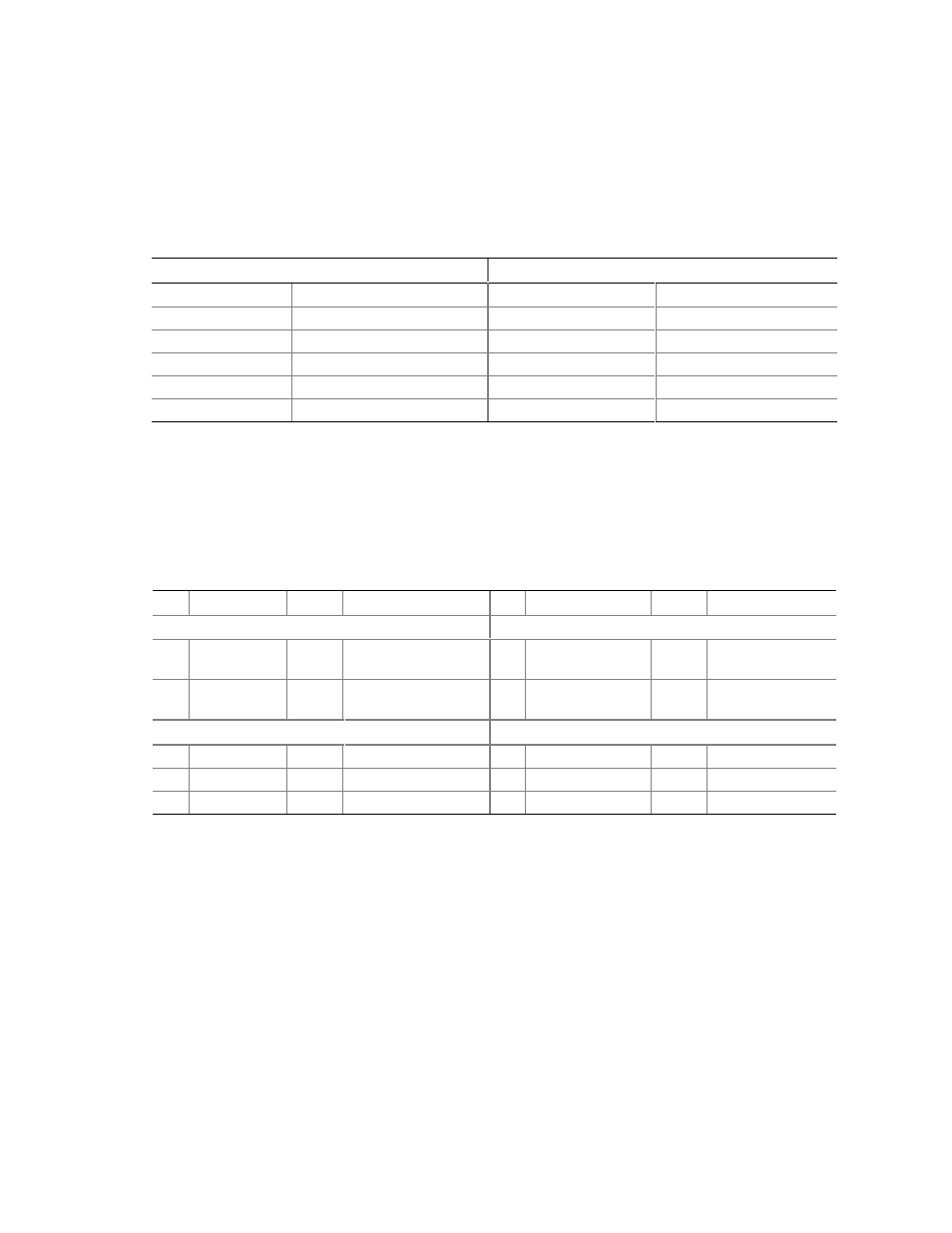
Connecting USB 2.0 Headers
Before connecting USB 2.0 headers, observe the precautions in “Before You Begin” on page 25.
Figure 13-A and -B on page 38 shows the location of the USB 2.0 headers. Table 9 shows the pin
assignments for the headers.
Table 9.
USB 2.0 Headers (J9F1 and J9H1)
USB Port A
USB Port B
Pin
Signal Name
Pin
Signal Name
1 Power
2
Power
3 D-
4
D-
5 D+
6
D+
7 Ground
8
Ground
9
Key (no pin)
10
Not connected
Note: USB ports may be assigned as needed.
Connecting the Front Panel Header
Before connecting the front panel header, observe the precautions in “Before You Begin” on
page 25. Figure 13-C on page 38 shows the location of the front panel header. Table 10 shows the
pin assignments for the front panel header.
Table 10. Front Panel Header (J9J1)
Pin Signal
In/Out Description
Pin Signal
In/Out Description
Hard Drive Activity LED
Power LED
1
HD_PWR
Out
Hard disk LED pull-
up (330
Ω) to +5 V
2
HDR_BLNK_GRN Out
Front panel green
LED
3
HDA#
Out
Hard disk active LED 4
HDR_BLNK_YEL
Out
Front panel yellow
LED
Reset Switch
On/Off Switch
5 Ground
Ground
6 SWITCH_ON# In
Power
switch
7 FP_RESET#
In
Reset
switch
8 Ground
Ground
9
+5 V
Out
Power
10
N/C
Not connected