Speaker connector information, Nspeaker connector information, Connection and maintenance – Icom IC-F9511HT User Manual
Page 26
21
3
CONNECTION AND MAINTENANCE
n
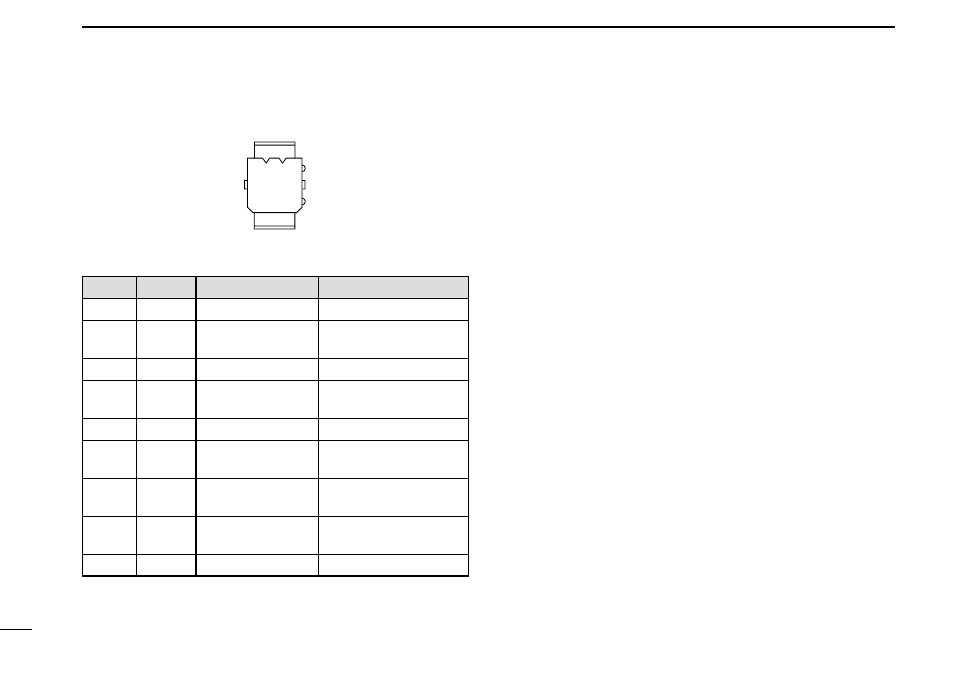
Speaker connector information
u i o
r t y
q w e
Connector’s front view
Pin No.
Name
Description
Specifications
q
IGN
IGSW cont. In
0 − Vcc
w
RXSP1 RX AF Out (BTL)
Output power : Max. 20 W
Impedance : 4 ø
e
NC
—
—
r
HORN1* Horn drive cont. Out
0 − Vcc
Output current: Max. 1 A
t
HORN2* Horn drive cont. Out 0 − Vcc
y
RXSP2 RX AF Out (BTL)
Output power : Max. 20 W
Impedance : 4 ø
u
PS1
AF Out to PA (BTL)
Output power : Max. 20 W
Impedance : 4 ø
i
PS2
AF Out to PA (BTL)
Output power : Max. 20 W
Impedance : 4 ø
o
GND
Connects to ground.
—
* When the horn function is activated, HORN1 and HORN2
are shorted.