Connection and maintenance, Separation cable connection, Nseparation cable connection – Icom IC-F9511HT User Manual
Page 19
14
3
CONNECTION AND MAINTENANCE
1
2
3
4
5
6
7
8
9
10
11
12
13
14
15
16
n
Separation cable connection
CAUTION: To avoid damage to the transceiver, disconnect
the DC power cable from the transceiver before connecting
the separation cable.
NOTE: The following connections should be performed by
your Icom dealer or distributor.
The supplied or optional separation cable is required for the
controller and the main unit connection.
See “OPTIONS” on page 22 for the separation cable details.
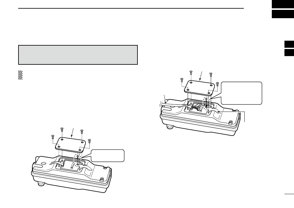
D Controller
q
Unscrew the 4 screws, then remove the rear plate from the
controller.
Unscrew the cir-
cuit board screw.
Controller
Rear plate
w
Connect the separation cable to the controller as shown
below.
• The cable can be inserted into either the left or right grooves as
desired.
Separation
cable
Rear plate
Cable
groove
Controller
Screw the removed
circuit board screw
in step q to connect
the cable terminal.
e
After the cable connection, replace the removed rear plate
and the 4 screws, then connect the opposite side of the
separation cable to the main unit. (See the next page)