Front press cable loop diagram – Impex CR 5 User Manual
Page 17
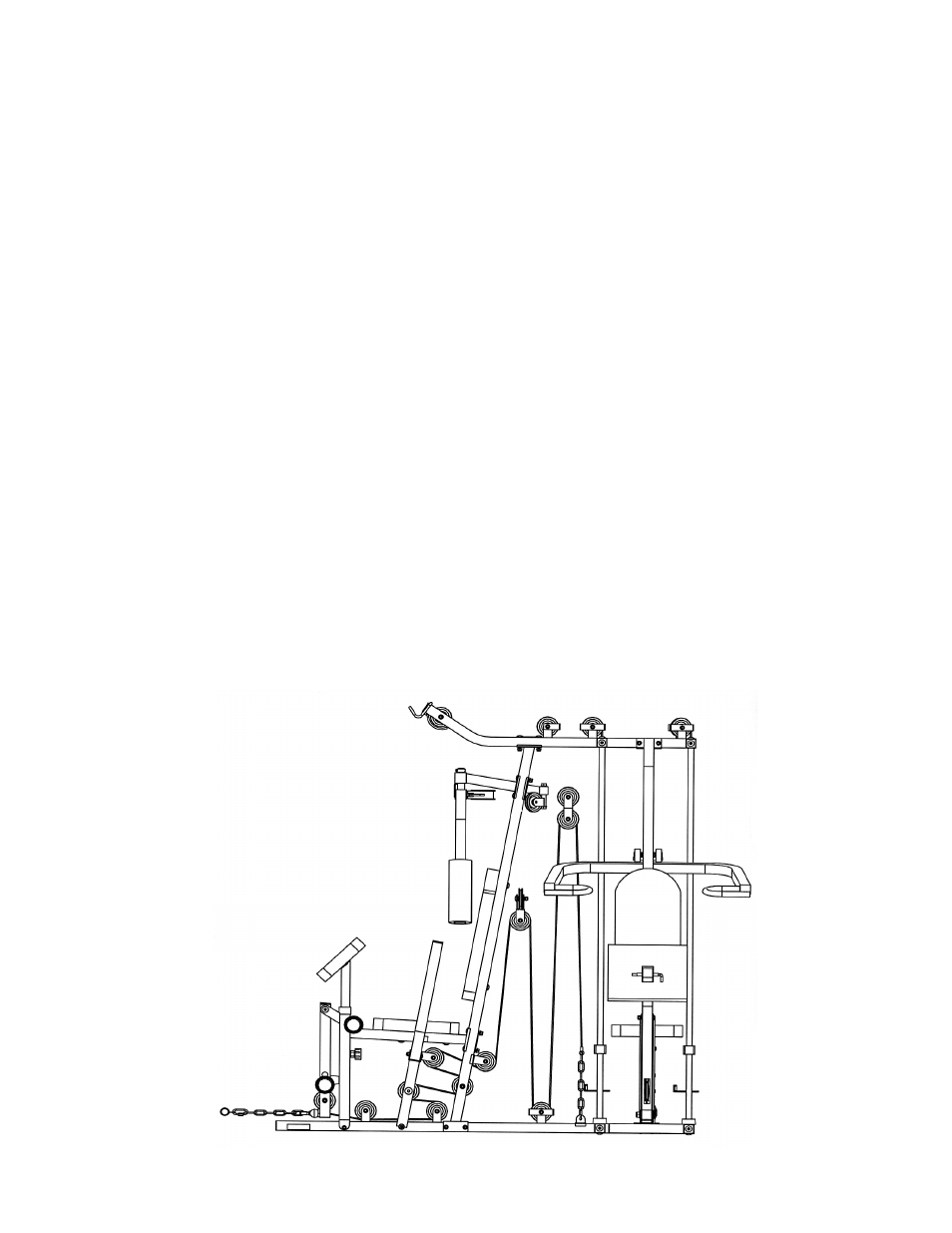
STEP 9 (See Front Press Cable Loop & Diagram 9)
A.) Attach the 247” Front Press Cable (#94) to the lower opening on the Leg Developer (#40).
B.) Attach a Pulley (#79) to the opening. Secure it with one M10 x 2 ½” Allen Bolt (#10), two
Pulley Bushings (#11), and one M10 Aircraft Nut (#5).
C.) Draw the Cable underneath the Pulley through the opening on the Right Seat Support (#49) to
the open bracket on the Right Base Frame (#46).
D.) Attach a Pulley to the bracket. Secure it with one M10 x 2” Allen Bolt (#98), two
∅
¾” Washers
(#6), and one M10 Aircraft Nut (#5).
E.) Continue drawing the Cable along the Right Base Frame to another open bracket. Install a
Pulley as described in Step D above with a L-shaped Pulley Bracket (#86). Draw the Cable
around the Pulley then back to the opening between the Front Press Base (#97).
F.) Attach a Pulley to the opening. Secure it with one M10 x 8 ¼” Allen Bolt (#62), two
∅
¾”
Washers (#6), and one M10 Aircraft Nut (#5).
G.) Draw the Cable around the Pulley then back to the lower opening on the Right Vertical Beam
(#21). Install another Pulley as described in Step D above. Draw the Cable back to the open
bracket on the back of Front Press Base.
H.) Install another Pulley as described in Step D above. Draw the Cable back through the lower
opening on the Right Vertical Beam (#21) to the open bracket on the back of the Beam. Install
another Pulley.
I.) Draw the Cable upward to the hanging Angled Double Floating Bracket (#51) previously
installed in STEP 8. Install another Pulley. Draw the Cable downward to the open bracket on
the Right Base Frame (#46). Install another Pulley with a U-shaped Pulley Bracket (#85).
J.) Draw the Cable upward to the hanging Flat Double Floating Pulley Bracket (#59) previously
installed in STEP 7. Install another Pulley.
K.) Draw the Cable around the Pulley then downward and connect to the Right Base Frame with a
Chain (#3) and two C-clips (#4). Adjust the tension of the Cable by adjusting the length of the
Chain.
FRONT PRESS CABLE LOOP DIAGRAM
16