Upper cable loop diagram – Impex CR 5 User Manual
Page 13
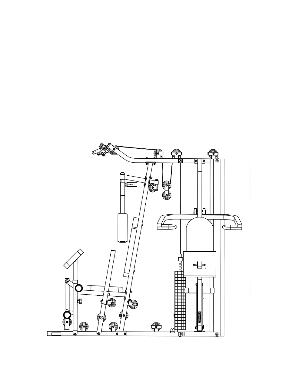
STEP 7 (Upper Cable Loop & Diagram 7)
A.) Attach the 108” Upper Cable (#93) to the front opening on the Upper Frame (#8). Attach a
Pulley (#79) to the opening. Secure it with one M10 x 2 ½” Allen Bolt (#10), two Pulley
Bushings (#11), and one M10 Aircraft Nut (#5). Draw the Cable towards the back of the
machine. Note: Make sure the Ball Stopper is underneath the frame.
B.) Attach a Pulley to the bracket on the Upper Frame. Secure it with one M10 x 2” Allen Bolt
(#98), two
∅
¾” Washers (#6), one L-shaped Pulley Bracket (#86), and one M10 Aircraft Nut
(#5).
C.) Pull the Cable downward. Install a Pulley with a Flat Double Floating Pulley Bracket (#59). Let
the bracket hanging for now.
D.) Draw the Cable around the Pulley then upward to the second open bracket on the Upper
Frame. Install another Pulley with a U-shaped Pulley Bracket (#85).
E.) Draw the Cable around the Pulley then downward to the Selector Rod (#69). Securely thread
the end of the Cable into the Selector Rod (#69).
UPPER CABLE LOOP DIAGRAM
12