Diagram 2 – Impex SM-4008 User Manual
Page 32
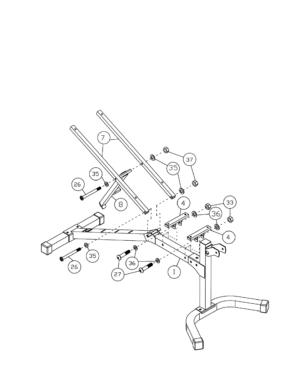
STEP 2 (See Diagram 2)
A.) Attach the Incline Support (#8) to the middle side holes on the two Backrest Supports (#7). Secure it
with one M10 x 6 7/8” Allen Bolt (#26), two Ø ¾” Washers (#35), and one M10 Aircraft Nut (#37).
Do not tighten the Nut and Bolt yet.
B.) Attach the bottom side holes on Backrest Supports to the pivot on Main Frame (#1). Secure it with
one M10 x 6 7/8” Allen Bolt (#26), two Ø ¾” Washers (#35), and one M10 Aircraft Nut (#37).
Securely tighten Nut and Bolt in A & B.
C.) Attach two Seat Brackets (#4) to the Main Frame. Secure each Seat Bracket with one M8 x 2 ¾”
Allen Bolt (#27), two Ø 5/8” Washers (#36), and one M8 Aircraft Nut (#33).
DIAGRAM 2
31
See also other documents in the category Impex Sports and recreation:
- IGS-09 (11 pages)
- SAG-44.1 (10 pages)
- TSA-5682 (14 pages)
- MWM-1840 (29 pages)
- IGS-10 (10 pages)
- TC-6000 (12 pages)
- MWB-715N (12 pages)
- CR 5 (26 pages)
- MD-823 (15 pages)
- PL-43211 (14 pages)
- PL 10510 (12 pages)
- WM-1505 (22 pages)
- PHE1000 (20 pages)
- TSA-5762 (14 pages)
- IGS-5683 (13 pages)
- DBR 400 (7 pages)
- MWM7150 (21 pages)
- DBR 90 (11 pages)
- CG 1400 (24 pages)
- SB 208 (9 pages)
- IGS-02 (10 pages)
- MWB-356 (13 pages)
- AX-PWR7 (21 pages)
- MWB-855 (11 pages)
- TSA-410 (10 pages)
- TSA-41 (7 pages)
- WM 1403 (22 pages)
- DBR 92 (11 pages)
- MARCY TPL-40 (3 pages)
- MSS-1280 (27 pages)
- JD 2 (8 pages)
- PHC-700 (12 pages)
- Gold's Gym WMGG-224 (11 pages)
- MWM 800 (23 pages)
- WM-356 (13 pages)
- EVE-720 (13 pages)
- BF-1201 (22 pages)
- PT 360 (9 pages)
- CB-200 (11 pages)
- Olympic Cage (24 pages)
- EVE-900 (21 pages)
- PT-36 (7 pages)
- PHC-PWR9 (22 pages)
- MWM-1558 (20 pages)
- MWB-4360 (33 pages)