Connecting speakers, Connecting the speaker, Connecting the speaker cable – Integra DTM-5.3 User Manual
Page 12: Connecting a subwoofer
12
Connecting speakers
Connecting the speaker
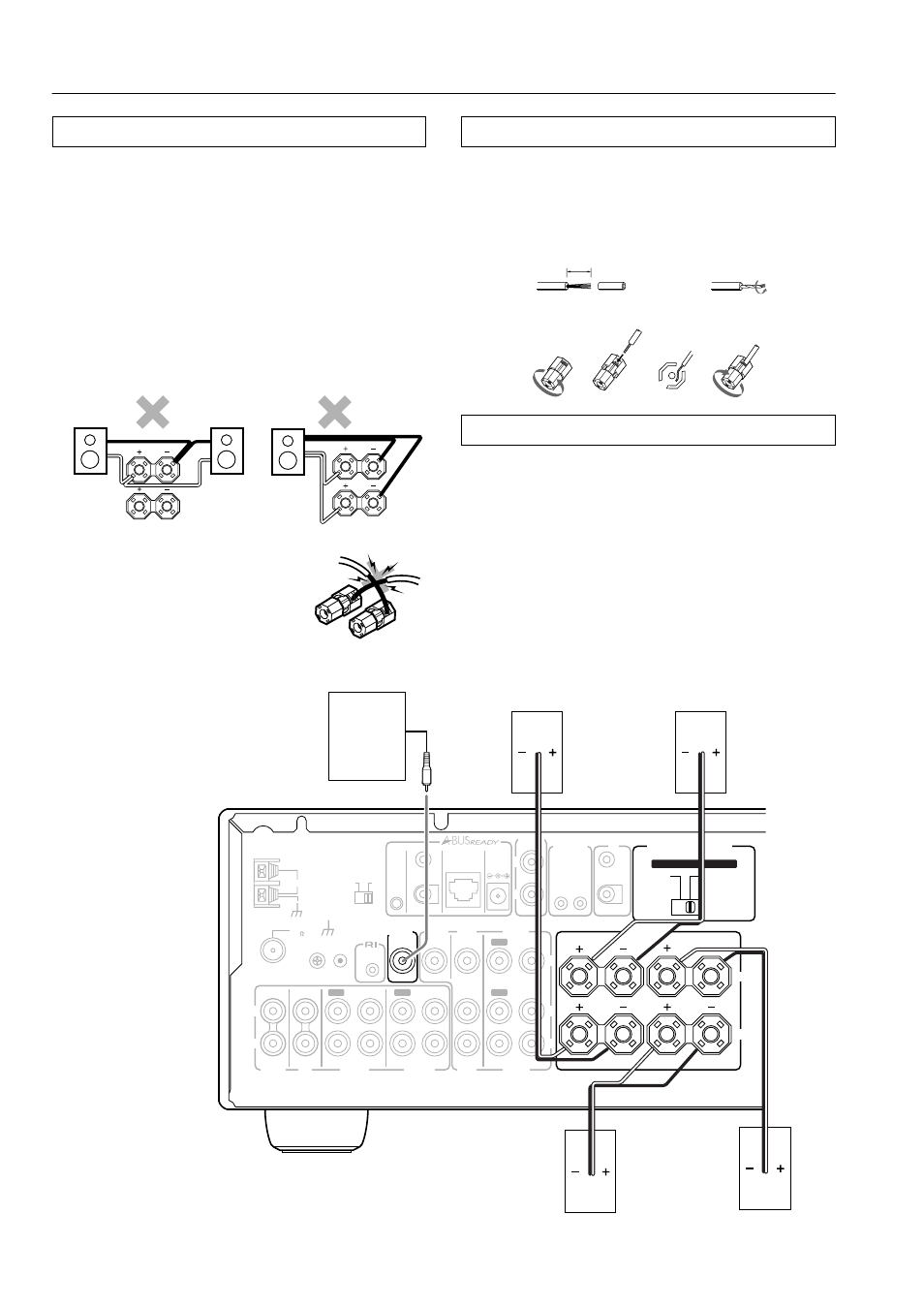
You can connect two separate pairs of speaker systems.
Please connect each speaker according to the illustration, observing
the correct connections for R, L, + and –.
Check the speaker impedance, then set the SPEAKER IMPEDANCE
SELECTOR switch accordingly. Refer to pages 8 and 9 for details.
Notes:
• Do not use unnecessarily long or extremely thin speaker leads.
If the DC resistance of the speaker leads is too high, the damp-
ing factor will decrease, adversely affecting the sound quality.
• When you are using only one speaker or when you wish to lis-
ten to monaural (mono) sound, a single speaker should never be
connected in parallel to both the right and left-channel terminals
simultaneously.
• To prevent damage to circuitry, never
short-circuit the positive (+) and nega-
tive (–) speaker wire.
•
Be sure to connect the positive and nega-
tive cables for the speakers properly. If
they are connected to the wrong terminal,
the left and right signals will be reversed
and the audio will sound unnatural.
• Do not connect more than one speaker
cable to one speaker terminal. Doing so
may damage the DTM-5.3.
Connecting the speaker cable
1. Strip away 5/8 inch (15 mm) of wire insulation.
2. Twist wire ends very tight.
3. Unscrew.
4. Insert wire.
5. Screw.
Connecting a subwoofer
Use the SUBWOOFER PRE OUT jack to connect a subwoofer
with a built-in power amplifier. If your subwoofer does not have a
built-in amplifier, connect an amplifier to the PRE OUT SUB-
WOOFER jack and the subwoofer to the amplifier.
Note:
The SUBWOOFER PRE OUT can only operate when speaker sys-
tem A is turned on.
B
SPEAKERS
R
L
B
SPEAKERS
R
L
NO
5/8 inch
(15 mm)
1
3
4
5
2
REMOTE
CONTROL
ANTENNA
OUT
A
B
IN
IN
IN
IN
OUT
IN
IN
OUT
OUT
A + B : 8 OHMS MIN.
/SPEAKER
A OR B :
8 OHMS MIN.
/SPEAKER
A OR B : 4 OHMS MIN.
/SPEAKER
FM
75
GND
ZONE 2
CONTROL
SELECTOR
IR OUT 40K
IR OUT
56K
ZONE 2
OUT
DC IN
24V 1A
IN
OUT
12 V
TRIGGER
IR
OUT
ZONE 2
SPEAKERS
VIDEO
DVD
MONITOR
OUT
PHONO
CD
TAPE 1
TAPE 2
VIDEO
DVD
V
R
L
R
L
A-BUS
IR
AM
R
L
SET BEFORE POWER ON
SPEAKER IMPEDANCE
SELECTOR
ZONE 2
OUT
IN
R
L
SUBWOOFER
PRE OUT
IN
IN
A
B
Subwoofer
SPEAKER A
SPEAKER B
Left ch.
Right ch.
Left ch.
Right ch.