Rj-21 connector – Multi-Tech Systems MVPFXS-16 User Manual
Page 155
MultiVOIP FXS User Guide
Cable Pinouts
155
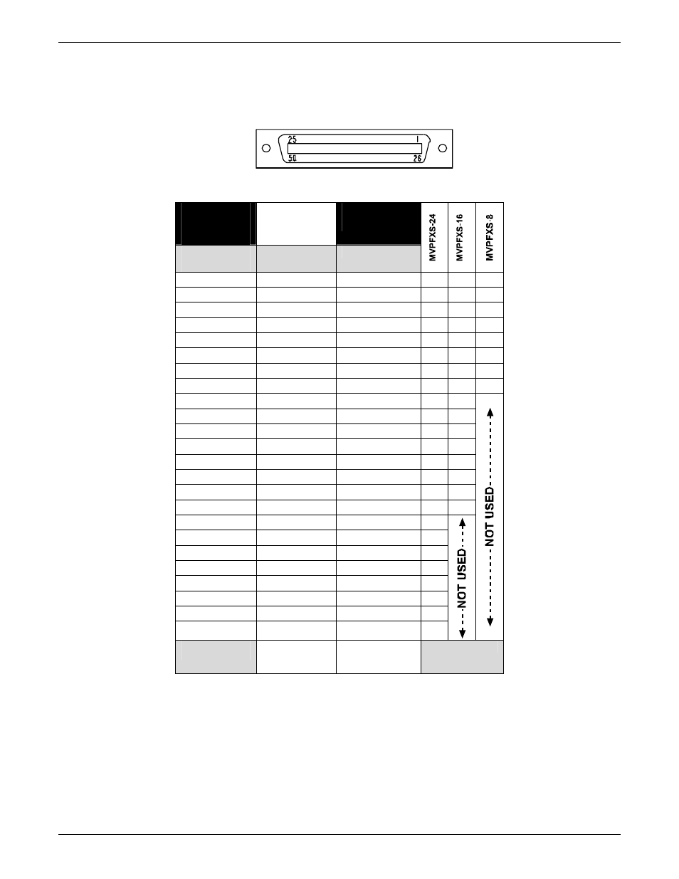
RJ-21 Connector
The footprint of the RJ-21 connector is shown in the figure below and its pin-out list is presented in the
table that follows.
RJ-21 Connector Footprint
RJ-21
Connector
Pin-Out List
TIP:
on Pins 1 – 24
RING:
on Pins 26 - 49
Wire Pairs for
Each Channel
Channel 1
1
26
√
√
√
Channel 2
2
27
√
√
√
Channel 3
3
28
√
√
√
Channel 4
4
29
√
√
√
Channel 5
5
30
√
√
√
Channel 6
6
31
√
√
√
Channel 7
7
32
√
√
√
Channel 8
8
33
√
√
√
Channel 9
9
34
√
√
Channel 10
10
35
√
√
Channel 11
11
36
√
√
Channel 12
12
37
√
√
Channel 13
13
38
√
√
Channel 14
14
39
√
√
Channel 15
15
40
√
√
Channel 16
16
41
√
√
Channel 17
17
42
√
Channel 18
18
43
√
Channel 19
19
44
√
Channel 20
20
45
√
Channel 21
21
46
√
Channel 22
22
47
√
Channel 23
23
48
√
Channel 24
24
49
√
Pin 25 is not
connected.
Pin 50 is not
connected.