Pin description (continued) – Maxim Integrated MAX12557 User Manual
Page 13
MAX12557
Dual, 65Msps, 14-Bit, IF/Baseband ADC
______________________________________________________________________________________
13
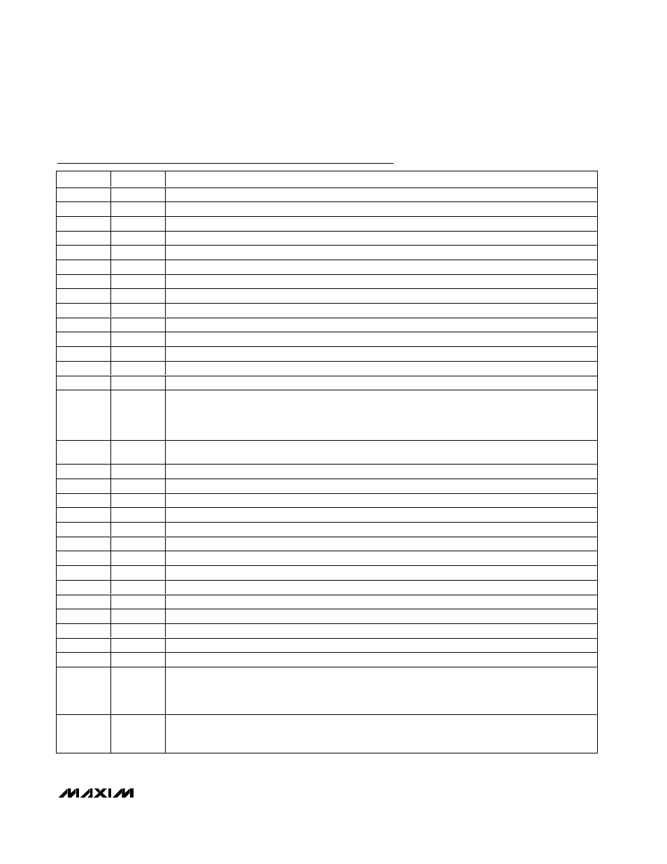
PIN
NAME
FUNCTION
28
D0B
Channel B CMOS Digital Output, Bit 0 (LSB)
29
D1B
Channel B CMOS Digital Output, Bit 1
30
D2B
Channel B CMOS Digital Output, Bit 2
31
D3B
Channel B CMOS Digital Output, Bit 3
32
D4B
Channel B CMOS Digital Output, Bit 4
33
D5B
Channel B CMOS Digital Output, Bit 5
34
D6B
Channel B CMOS Digital Output, Bit 6
35
D7B
Channel B CMOS Digital Output, Bit 7
36
D8B
Channel B CMOS Digital Output, Bit 8
37
D9B
Channel B CMOS Digital Output, Bit 9
38
D10B
Channel B CMOS Digital Output, Bit 10
39
D11B
Channel B CMOS Digital Output, Bit 11
40
D12B
Channel B CMOS Digital Output, Bit 12
41
D13B
Channel B CMOS Digital Output, Bit 13 (MSB)
42
DORB
Channel B Data Out-of-Range Indicator. The DORB digital output indicates when the channel B analog
input voltage is out of range.
DORB = 1: Digital outputs exceed full-scale range.
DORB = 0: Digital outputs are within full-scale range.
44
DAV
Data-Valid Digital Output. The rising edge of DAV indicates that data is present on the digital outputs.
The MAX12557 evaluation kit utilizes DAV to latch data into any external back-end digital logic.
45
D0A
Channel A CMOS Digital Output, Bit 0 (LSB)
46
D1A
Channel A CMOS Digital Output, Bit 1
47
D2A
Channel A CMOS Digital Output, Bit 2
48
D3A
Channel A CMOS Digital Output, Bit 3
49
D4A
Channel A CMOS Digital Output, Bit 4
50
D5A
Channel A CMOS Digital Output, Bit 5
51
D6A
Channel A CMOS Digital Output, Bit 6
52
D7A
Channel A CMOS Digital Output, Bit 7
53
D8A
Channel A CMOS Digital Output, Bit 8
54
D9A
Channel A CMOS Digital Output, Bit 9
55
D10A
Channel A CMOS Digital Output, Bit 10
56
D11A
Channel A CMOS Digital Output, Bit 11
57
D12A
Channel A CMOS Digital Output, Bit 12
58
D13A
Channel A CMOS Digital Output, Bit 13 (MSB)
59
DORA
Channel A Data Out-of-Range Indicator. The DORA digital output indicates when the channel A analog
input voltage is out of range.
DORA = 1: Digital outputs exceed full-scale range.
DORA = 0: Digital outputs are within full-scale range.
64
G/T
Output Format Select Digital Input.
G/T = GND: Two’s-complement output format selected.
G/T = OV
DD
: Gray-code output format selected.
Pin Description (continued)