Vent installation, How to use the vent graph – Mastic Spark Modern Fires 91P User Manual
Page 16
16
L100001
17
�
�
���� �������
�
���� �������
�
�
�
� � ����������� ����������
�������������� ����������
����������� �
��������������
� � ��� �������
� � ��� �������
�
�
�
� � ������� ����� �� ��� ��������
��� ������ ��������
� � ������� ����� ��� ���� ���� ��
������ ��������
����������� � ��� �������
�������������� � ��� �������
� � ��������� ���� ������ �� ������
��������
����������� � �� �������
�������������� � �� ������
�
�
�
�
�
������ ������
������ ��������
������� ������
������� ���� �� ���� ����
������� ���� �������������
���� ����
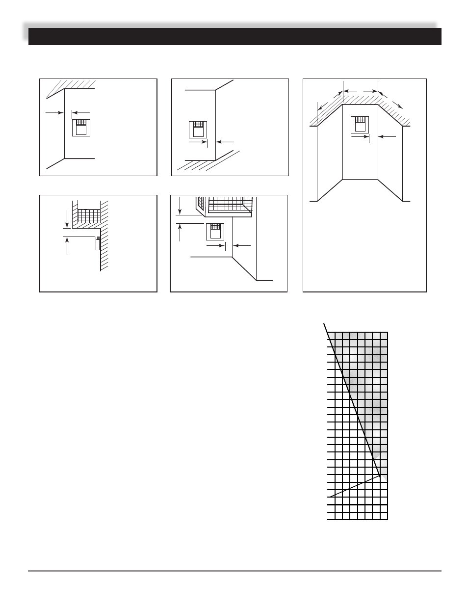
VENT INSTALLATION
TERMINATION CLEARANCES FOR BUILDINGS WITH COMBUSTIBLE
AND NONCOMBUSTIBLE EXTERIORS
Figure 9 - Allowable Venting Chart
HOW TO USE THE VENT GRAPH
The Vent Graph should be read in conjunction with the following
vent installation instructions to determine the relationship between
the vertical and horizontal dimensions of the vent system.
1. Determine the height of the center of the horizontal vent pipe exit-
ing through the outer wall. Using this dimension on the Sidewall
Vent Graph below, locate the point intersecting with the slanted
graph line.
2. From the point of this intersection, draw a vertical line to the
bottom of the graph.
3. Select the indicated dimension, and position the fireplace in
accordance with same.
Example: If the vertical dimension from the floor of the
fireplace is 11' (3.4m) the horizontal run to the face of the
outer wall must not exceed 14' (4.3m).
Example: If the vertical dimension from the floor of the unit
is 7’ (2.14m), the horizontal
wall must not exceed 7 ' (2.14m).
run to the face of the outer
Sidewall Vent Graph showing the relationship between vertical and
horizontal dimensions for a Direct Vent flue system.
Figure 10 - Rear Wall Venting Graph
Horizontal Dimension (Ft) From the Outside of
Termination to the Back of the Fireplace
V
ertical Dimension
(
Ft)
From the Floor of Unit to the Center of
the Horizontal V
ent Pipe
Dimensions in Feet
50
48
46
44
42
40
38
36
34
32
30
28
26
24
22
20
18
16
14
12
10
8
6
4
2
2 4 6 8
16
14
12
10