English, Iii. assembly – Middleby Cooking Systems Group PS536 User Manual
Page 9
9
ENGLISH
SECTION 2 - INSTALLATION
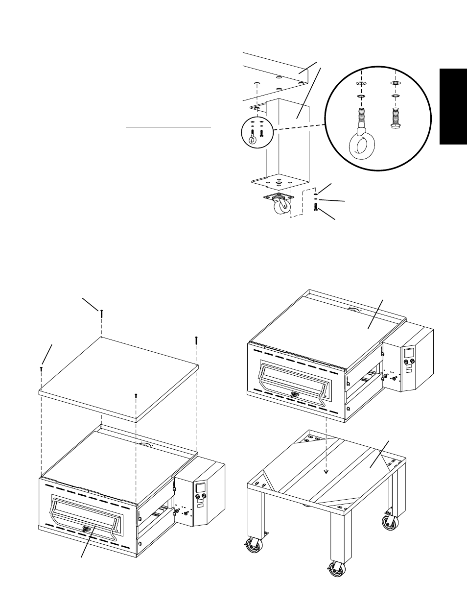
III. ASSEMBLY
A. Top Panel and Base Pad Assembly
1. Install the four leg extensions onto the base pad using the
3/8"-16x1" screws, 3/8" flat washers, and 3/8" lockwashers
supplied in the Base Pad Kit. See Figure 2-3. Check that
the finished sides of each leg extension face OUTWARDS.
One rear leg should be attached using three 3/8"-16 x 1"
screws and the 3/4" eyebolt, as shown in Figure 2-3. This
eyebolt acts as the anchor point for the restraint cable
assembly (see Part C, Restraint Cable Installation).
2. Install one caster onto each leg extension, as shown in
Figure 2-4. Use the 3/8"-16x1" screws, 3/8" flat washers,
and 3/8" lockwashers supplied in the Installation Kit. The
locking casters should be installed at the FRONT of the
oven. The non-locking casters should be installed at the
REAR of the oven.
3. Install the top panel in place on the top oven cavity using the
screws included in the base pad kit, as shown in Figure 2-
4.
4. Install the lower oven cavity onto the base pad. Check that
the eyebolt welded onto the pad faces the rear of the oven.
Figure 2-3 - Leg extension and casters installation
Locking casters -
FRONT of oven
Non-locking casters -
REAR of oven
3/8" flat
washer
3/8" lock
washer
3/8"-16 x 1"
hex screw
3/8" flat
washer
3/8" lock
washer
3/8"-16 x 1"
hex screw
Finished sides of
leg extension
face corner of
base pad
3/4" eyebolt
(inside corner of
one rear leg
extension
only)
Figure 2-4 - Top panel and base pad installation
#10 x 1" screws
attach front of
top panel
#10 x 2" screws
attach rear of
top panel
Top oven
cavity
Bottom oven
cavity
Assembled
base pad