English – Middleby Cooking Systems Group PS536 User Manual
Page 10
10
ENGLISH
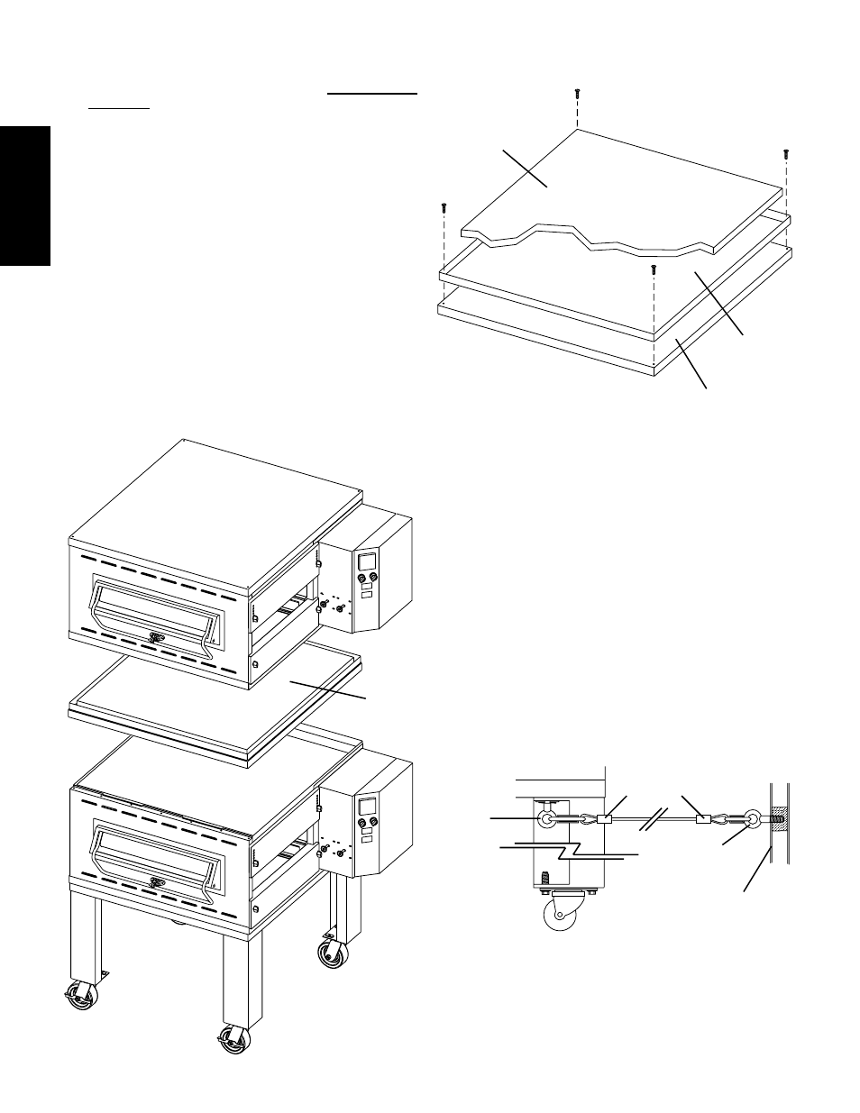
C. Restraint Cable Installation
Because the oven is equipped with casters, a restraint cable
assembly must be installed to limit the movement of the
appliance without depending on the connector and the quick
disconnect device or its associated piping. One end of the cable
is anchored to the eyebolt on one of the rear leg extensions,
while the other is anchored to the wall. See Figure 2-7.
After connecting the restraint cable, move the oven to its final
location. Then, lock the two front casters.
3/8"-16 x 1"
eyebolt on
rear leg
extension
Restraint cable
assembly
3/4 (19mm)
eyebolt
Wall of
structure
Figure 2-7 - Installing the Restraint Cable
B. Stacking
For single ovens, skip ahead to Part C, Restraint Cable
Installation. For double or triple ovens, continue on to Step
1, below.
1. Assemble the stacking spacer(s) as shown in Figure 2-5.
One spacer assembly is supplied for a double oven, while
two are supplied for a triple oven.
2. Place one of the assembled spacers on top of the lower
oven cavity, making sure that the insulation faces up.
3. Place the center oven cavity (for triple ovens) or the top oven
cavity (for double ovens) on top of the spacer. Check that
all four sides of the spacer overlap the base of the oven, and
that the oven is level and firmly seated. See Figure 2-6.
4. For triple ovens, repeat Steps 2 and 3 to install the top oven
cavity.
Figure 2-5 - Assembling the stacking spacers
#10-32 x 1/2"
hex screws
1-1/2" (38mm)-thick
insulation, pre-cut
Stacking panel,
P/N 44837
Top panel,
P/N 42882
Figure 2-6 - Stacking
Assembled
spacer
(insulation
faces up)
SECTION 2 - INSTALLATION