MITSUBISHI ELECTRIC MSZ-FD25VAS User Manual
Page 23
23
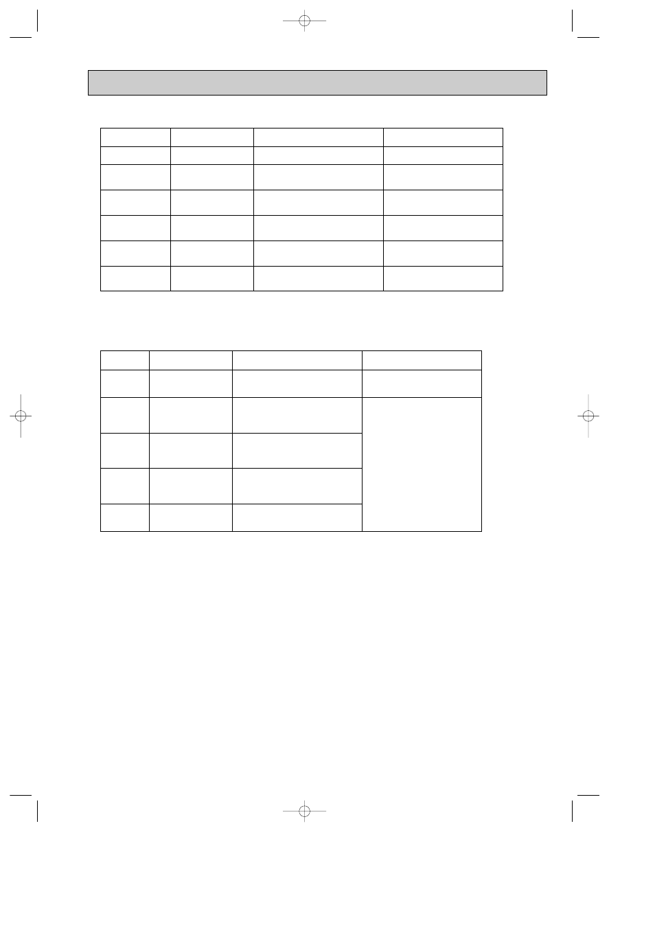
4. Indoor unit failure mode table
NOTE : Blinking patterns of this mode differ from the ones of TROUBLESHOOTING CHECK TABLE (10-4.).
12-time flash
2.5-second OFF
Replace the indoor electronic control
P.C. board.
Indoor control system
It cannot properly read data in the
nonvolatile memory of the indoor electronic
control P.C. board.
11-time flash
2.5-second OFF
Refer to 10-6.
A
"Check of indoor fan
motor".
Indoor fan motor
The rotational frequency feedback signal is
not sent out for 12-seconds after indoor fan
motor is operated.
2-time flash
2.5-second OFF
Refer to the characteristics of the main
indoor coil thermistor, the sub indoor coil
thermistor (10-7.).
Indoor coil thermistor
The indoor coil thermistor short or open
circuit is detected every 8 seconds during
operation.
3-time flash
2.5-second OFF
Refer to 10-6.
D
"How to check miswiring
and serial signal error".
Serial signal
The serial signal from outdoor unit is
not received for 6 minutes.
1-time flash
every 0.5-second
Refer to the characteristics of the room
temperature thermistor (10-7.).
Room temperature
thermistor
The room temperature thermistor short
or open circuit is detected every 8 seconds
during operation.
Not lighted
—
Normal
—
POWER lamp
Correspondence
Abnormal point
(Failure mode)
Condition
5. PLASMA operation failure mode table
5-time flash
The voltage between CN1
3
(+) and
2
(GND)
on the PLASMA POWER P.C board rises
above the normal voltage value (3 V).
4-time flash
PLASMA DEODORIZING
The voltage between CN1
3
(+) and
2
(GND)
on the PLASMA POWER P.C.board falls
significantly. (0.4 V / 0.5 ms)
3-time flash
Refer to 10-6.
F
"Check of PLASMA
operation".
Abnormal electric
discharge error 1
The voltage between CN1
3
(+) and
2
(GND)
on the PLASMA POWER P.C.board falls by
0.9 V below the normal voltage value (3 V).
2-time flash
Spark discharge
1-time flash
PLASMA power supply
control
The voltage between CN1
3
(+) and
2
(GND)
on the PLASMA POWER P.C.board falls
below 1.6 V(spark discharge judgment
voltage).
PLASMA power supply cannot be turned
OFF even if the PLASMA operation is turned
OFF with the remote controller.
POWER lamp
Correspondence
Abnormal point
(Failure mode)
Condition
Abnormal electric
discharge error 2
Replace the indoor electronic control
P.C.board.
NOTE1 : Blinking patterns of this mode differ from the ones of TROUBLESHOOTING CHECK TABLE (10-4.).
NOTE2 : As soon as an abnormality is detected, PLASMA operation goes OFF, therefore measuring
instrument which records the voltage wave is required in order to perform the above mentioned voltage
measurement.
NOTE3 : When POWER lamp flashes 1-time or 2-time, Please perform PLASMA operation check (Refer to 10-2.3).
OBH488-1.qxp 07.8.9 4:52 PM Page 23