Mod 8 adapter note, Calibration connections – Microtest TSB-67 - 568A Annex E User Manual
Page 9
Page 9
be calibrated each calendar day that it is used. Expiration of calibration data is automatically
detected by the Scanner.
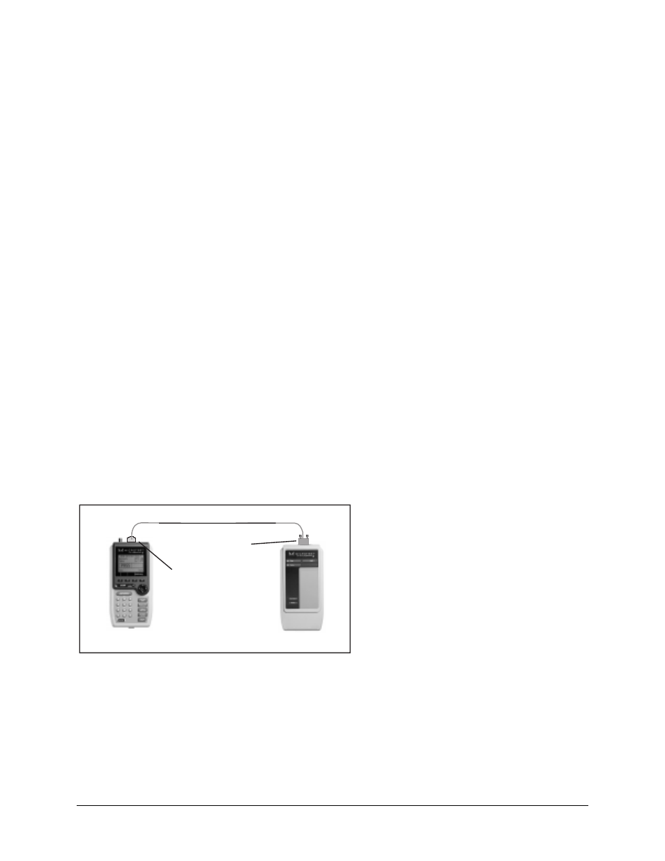
The Scanner and Injector are connected through their respective test connector ports using the
patch cable provided with each instrument. The amplitude of each frequency generated by the
Injector is measured by the Scanner. The resulting calibration values are stored in the Scanner
according to the Injector’s serial number. The Scanner maintains five sets of Injector calibration
data simultaneously.
1.
Connect the Scanner and the Injector using the patch cable supplied with the Scanner (see
following diagrams). If you have a Scanner with a 36-pin connector, you may also need to use
the Mod 8 Adapter (included).
2.
Power on the Scanner.
3.
Press the
Extended Functions
key.
4.
Select
Calibrate Injector
. The Scanner will display:
Searching for Injector . . .
5.
On finding the Injector, the Scanner displays:
Calibrating . . .
6.
When the calibration is complete, the Scanner displays:
The Injector has been calibrated
7.
Press
OK (F1)
to return to the
Extended Functions
menu.
Mod 8 Adapter Note
Use of the mating connectors not in conformance with FCC Part 68, Sub-Part F may result in
damage not covered by Microtest warranty.
Calibration Connections
Modular 8 Plug to
36-Pin Patch Cable
36-Pin Injector
36-Pin Scanner
Modular 8 Adapter