Garland 200 User Manual
Page 89
Part # MCOSM06 Rev 1 (11/03/08)
Page 89
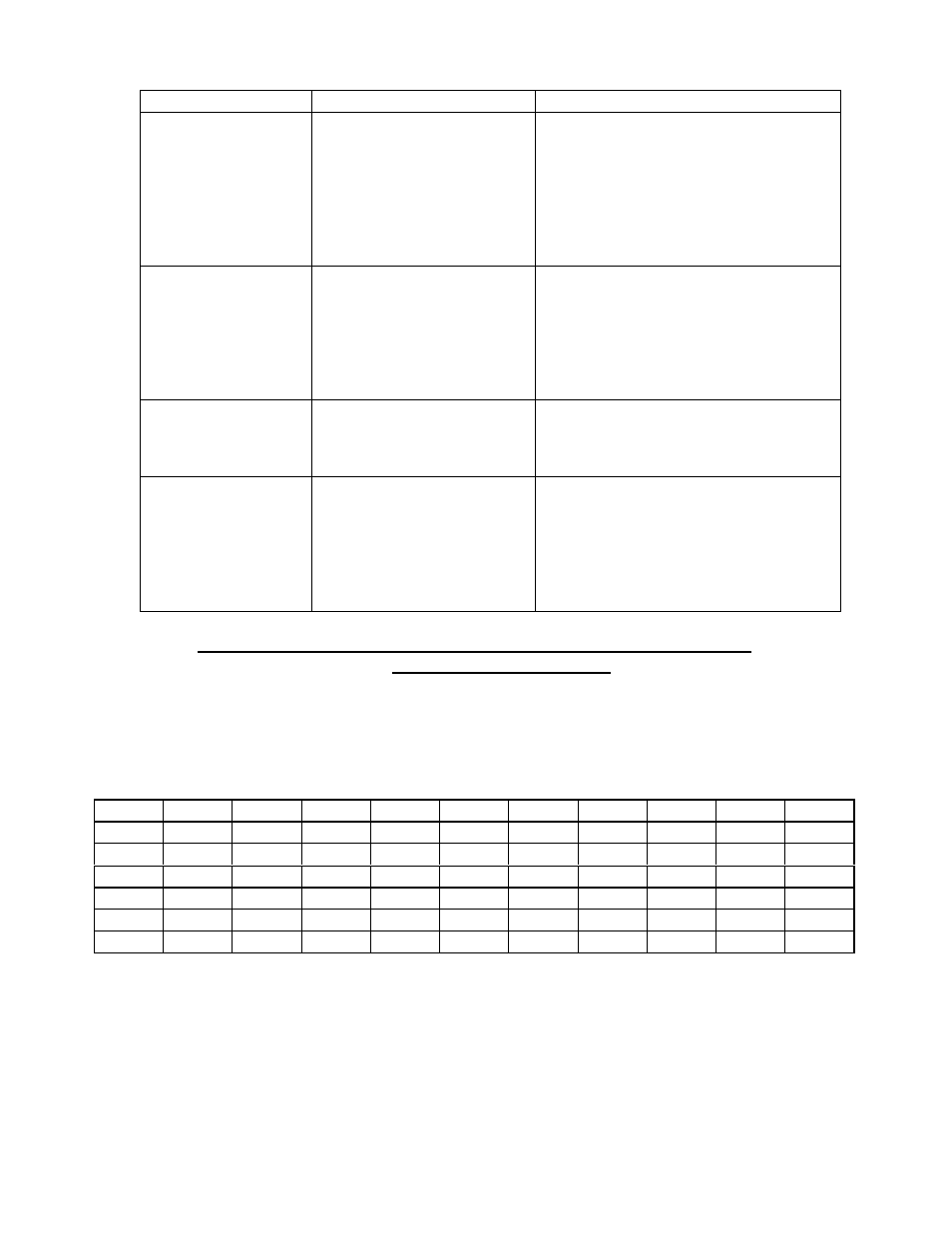
Problem
Possible Cause
Corrective Action
No display
A. No power to smart
board
B. No power to relay board
A. Check for 24VAC between pins 1
and 3 on smart board. If voltage
present check for 24VAC at pins 1
and 3 at relay board
B. Check for 24VAC into relay board
and 24VAC out of relay board
between pins 1 and 3 on relay
board
Fan runs for a period
of time, shuts down
then comes back on
after several minutes
A. motor has tripped on
internal thermal
overload
A. check for a minimum 6” clearance
at rear of unit to a wall or heat
source
B. Check air intake vents on back of
motor for obstructions
C. If problem persists and above have
been corrected replace motor assy
Timer slow counting
down
A. Timer is in hours / min
A. Refer to operations manual or
bulletin # B-19-2001 on how to
change from hour / min to min /
seconds
Temperature out of
calibration
A. 400 series controllers
B. 200 & 300 series
controllers
C. Potentiometer defective
A. Confirm oven cavity temp with
resistance chart. If out by more
than 20 Ohms replace probe
B. Calibration can be performed by
repositioning temperature dial.
C. Check for proper ‘sweep’ on
potentiometer. 0 to 10.25KOHMS
RESISTANCE vs. TEMPERATURE CHART FOR INTERNAL OVEN
TEMPERATURE SENSOR
The chart below will provide the Ohms at various temperatures. This will enable
you to determine if the temperature probe is operable.
The chart is degrees Fahrenheit.
TEMP
0°
10°
20°
30°
40°
50°
60°
70°
80°
90°
0°
932
953
974
995
1016
1038
1059
1080
1101
1122
100°
1143
1163
1184
1205
1226
1247
1267
1288
1309
1329
200°
1350
1370
1391
1411
1432
1452
1472
1493
1513
1533
300°
1553
1574
1594
1614
1634
1654
1674
1694
1714
1733
400°
1753
1773
1793
1813
1832
1852
1871
1981
1911
1930
500°
1949
1969
1988
2008
2027
2046
2065
2085
2104
2123
Page 3 of 9
1-800-427-6668 www.garland-group.com Fax: 1-800-361-7745