Garland 200 User Manual
Page 31
Part # MCOSM06 Rev 1 (11/03/08)
Page 31
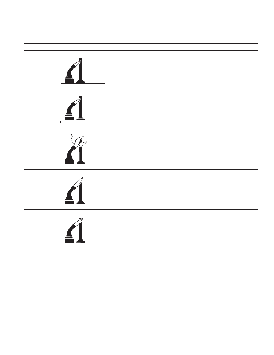
Examples Of Unsatisfactory Pilot Flames.
APPEARANCE
CAUSE
SMALL BLUE FLAME
Check for lack of gas from:
• Clogged orifice filter
• Clogged pilot filter
• Low gas supply pressure
• Pilot adjusted at the minimum
LAZY YELLOW FLAME
Check for lack of air from:
• Large orifice
• Dirty lint screen, if used
• Dirty primary air opening, if there is one
• Pilot adjusted at minimum
WAVING BLUE FLAME
Check for:
• Excessive draft at pilot locations
• Recirculating products of combustion
NOISY LIFTING BLOWING FLAME
Check for:
• High gas pressure
HARD SHARP FLAME
This flame is characteristic of manufactured gas
Check for:
• High gas pressure
• Orifice too small
Control Module Flame Sensor Circuit.
The control module provides AC power to theigniter/sensor
that the pilot burner flame rectifies to a direct current. If the
flame signal back the control module is not at least 1.0 μA
DC, the system will lockout. The output of the flame sensing
circuit cannot be checked directly, so check the flame sensing
circuit indirectly by checking the flame sensing current from
the igniter/sensor to the control module as follows:
1. Connect a meter (DC micrometer scale) in a series with
the flame signal ground wire (Burner Ground Terminal).
Disconnect the ground wire at the control module. Connect
the red (positive) lead of the meter to the free end of the
ground wire. Connect the black (negative) meter lead to the
quick-connect ground terminal on the control module.
2. Restart the system and read the meter. The flame sensor
currant must be at least 1.0 μA, and the reading must be
steady. If the reading is below the value designated or the
reading is unsteady, check the pilot flame and electrical
connection. Also, replace the igniter/sensor if the ceramic
insulator is cracked.