Probes – Garland 200 User Manual
Page 51
Part # MCOSM06 Rev 1 (11/03/08)
Page 51
PROBES
Oven Cavity Probe
Resistance vs . Temperature Chart For Internal Oven Cavity
Temperature Sensor .
The chart below will provide the Ohms at various
temperatures. This will enable you to determine if the
temperature probe is operable.
The chart is degrees Fahrenheit.
TEMP
0°
10°
20°
30°
40°
50°
60°
70°
80°
90°
0°
932
953
974
995
1016
1038
1059
1080
1101
1122
100°
1143
1163
1184
1205
1226
1247
1267
1288
1309
1329
200°
1350
1370
1391
1411
1432
1452
1472
1493
1513
1533
300°
1553
1574
1594
1614
1634
1654
1674
1694
1714
1733
400°
1753
1773
1793
1813
1832
1852
1871
1891
1911
1930
500°
1949
1969
1988
2008
2027
2046
2065
2085
2104
2123
Resistance Readings
77°F
=
1000 ohms
100°F =
1103 ohms
200°F =
1350 ohms
300°F =
1554 ohms
350°F =
1654 ohms
400°F =
1753 ohms
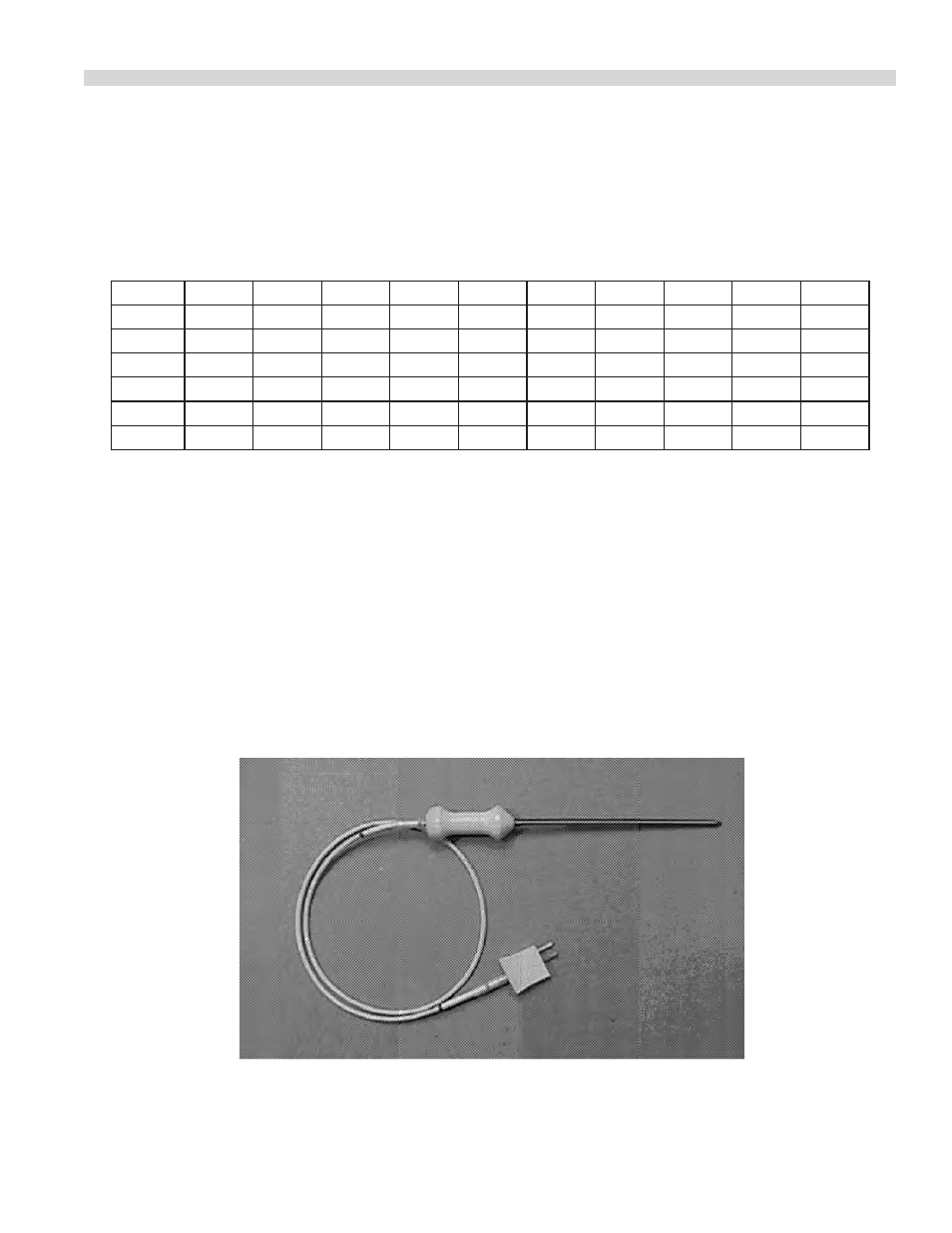
NOTE: If the cavity core probe is used, the core probe Led will
be lit on the control panel, the temperature of the product
will be displayed if the product is about 32°F.
The programmed range for the core probe is 100°F to 200°F.
Cavity Core Probe (455 Only)