Garland 200 User Manual
Page 55
Part # MCOSM06 Rev 1 (11/03/08)
Page 55
Testing
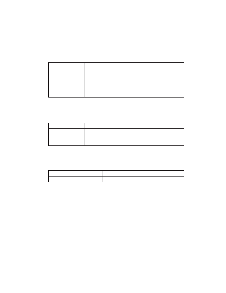
Test Points at 15 Pin Molex Connection
Through the back side of the Molex Connection with both the controller and the Relay
board connected:
Power to Controller
Pin 1 (white) & Pin 3 (white)
24 v.a.c. ±10%
Door Switch
SW1 for HEAT
(Upper Switch)
Pin 9 (black) & Pin 10 (white/gray)
5 v. a..c. ±10%
Door Switch SW2
for COOL
(Lower Switch)
Pin 9 (black) & Pin 12 (grey)
5 v. a..c. ±10%
The Next Pin Tests are Key Function Specific
(Criteria: You must activate the switch you are testing)
Fan High
Pin 5 (red) & Pin 7 (orange/white)
24 v.a.c. ±10%
Fan Low
Pin 5 (red) & Pin 8 (orange)
24 v.a.c. ±10%
Heat Demand
Pin 5 (red) & Pen 4 (white/violet)
24 v.a.c. ±10%
Oven Light
Pin 5 (red) & Pin 6 (violet)
24 v.a.c. ±10%
The Next tests are Ohm Readings
Criteria: You must disconnect the probes and test probes only.
Cavity probe open (oven)
See RTD chart under Probes this section
Core Probe (meat)
See chart under Probes, this section