Display, Key pad test – Garland 200 User Manual
Page 52
Page 52
Part # MCOSM06 Rev 1 (11/03/08)
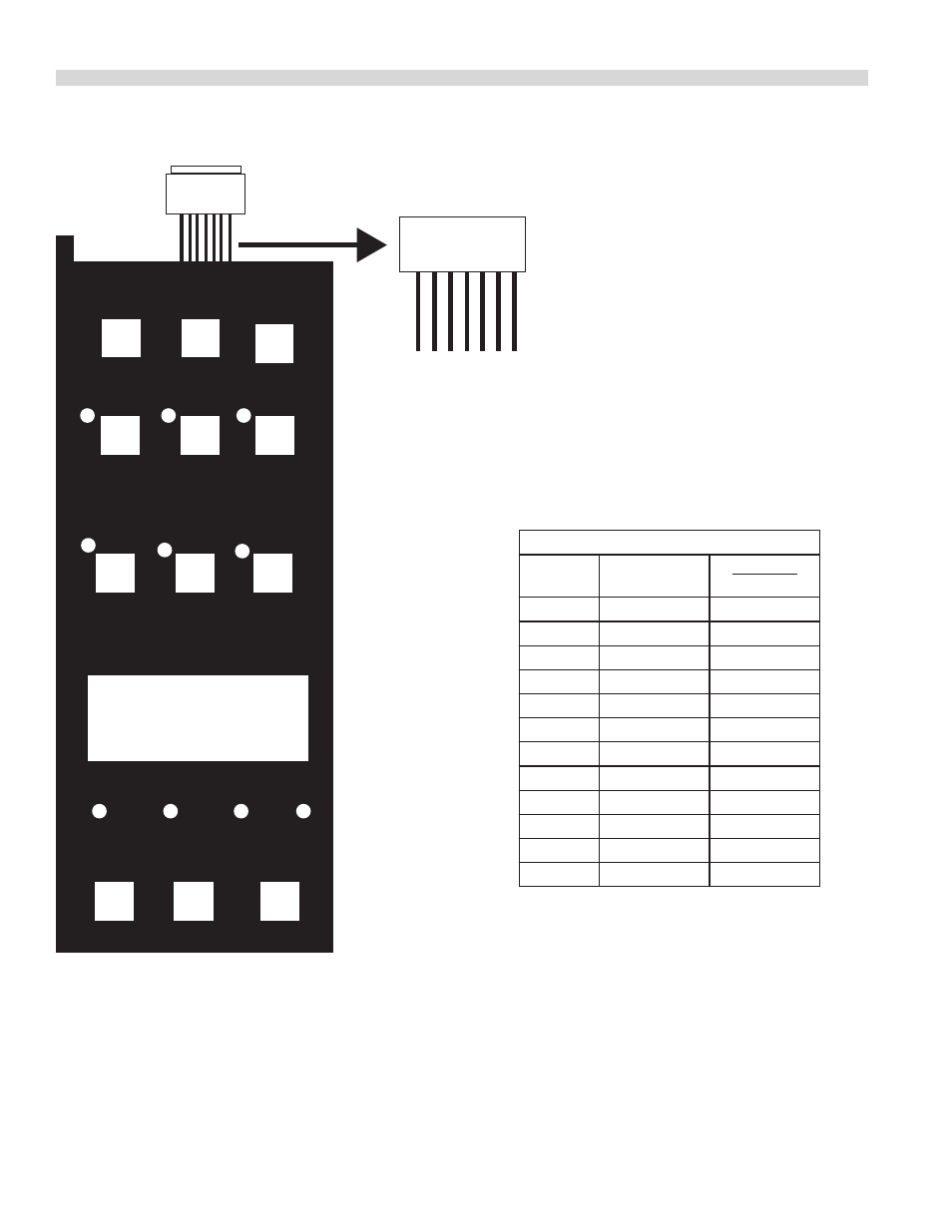
KEY PAD TEST
Key
#9
Key
#5
Key
#1
Key
#10
Key
#6
Key
#2
Key
#12
Key
#8
Key
#4
Key
#11
Key
#7
Key
#3
DISPLAY
Ribbon
Connector
PIN DETAIL
VIEWED FRON FRONT
PIN NUMBERS
On Ribbon
Connector
7 6 5 4 3 2 1
KEYPAD & TEST
POINTS VIEWED
FRON FRONT
PIN- OUT TEST POINTS
Key #
PIN-OUTS
OVERLAY
MARKINGS
1
1 & 4
SET BACK
2
1 & 5
COOL DOWN
3
1 & 6
PROGRAM
4
1 & 7
ACTUAL TEMP
5
2 & 4
CAVITY LIGHT
6
2 & 5
FAN LOW
7
2 & 6
COOK / HOLD
8
2 & 7
SET
9
3 & 4
ON / OFF
10
3 & 5
FAN HIGH
11
3 & 6
PULSE
12
3 & 7
START/CANCEL
Between the above pin test points on the ribbon connector,
there should be continunty when the corresponding key is
pressed.
EXAMPLE: When Key # 1 is pressed and held, there should be
continunity between pins 1 & 4 at the ribbon cable.
NOTE: The keypad must be attached to the control panel
bezel when tested . The keypad is grounded to the panel to
complete the circuit . Disconnec the ribbon connector from
the SMART BOARD / CONTROLLER to gain better access to
teest points .
Not all overlays will have the above-indicated markings .