GarrettCom Magnum 3000 User Manual
Page 21
Magnum 3000 Stackable Hubs Installation and User Guide (07/06)
14
www GarrettCom com
.
.
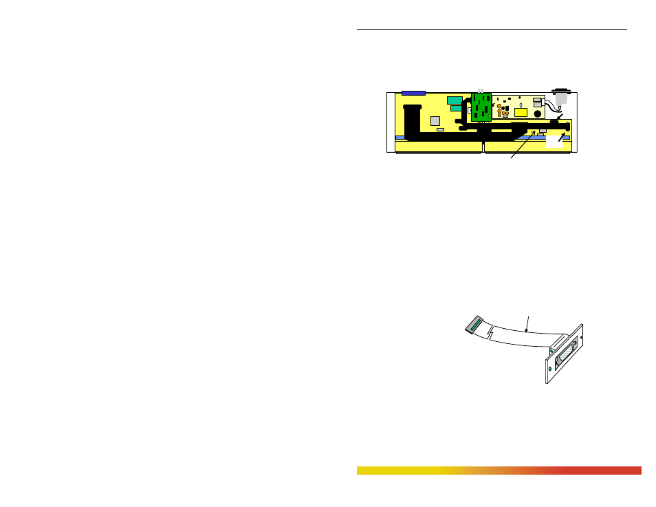
When installing a PM into the Bonus Port slot of the Magnum 3024, use the
16-pin header labeled P1 (also labeled RPM) on the circuit board corresponding to ports
13-24. The red stripe of the connector cable should connect to pin 1 of header P1.
NOTE: The PM will still function if connected to header J1/B of the circuit board
corresponding to ports 1-12. However, this is not advised, as the port will not be
recognized by an SNMP Agent (if one is present).
Figure 2.5d: Magnum 3024 internal layout with configured Bonus Port
CBL-AUI
When the RPM-AUI is factory configured as a bonus port, it is implemented
with CBL-AUI, an AUI
connector with a ribbon cable, to
the 16-pin header J1 (AUI) on
the main board (Shown in both
figure 2.5a and 2.5b). Since the
AUI functionality is build onto
the main board, using CBL-AUI
is identical to the RPM-AUI. GCI recommends that RPM-AUI units should not get
installed in the bonus port of both 3012’s and 3024’s.
Bonus port for optional
PM card (BPM shown)
PM Ribbon cable with 16 pin connector.
(Included only when PM is factory
May be ordered separately as part # CBL-PM)
NOTE:
Use J1 (AUI) and for Basic AUI ports
Use P1 (RPM) for PMs
J1
(AUI)
P1
(RPM)
Pin 1 (red)
CBL-AUI