Garrett – GarrettCom 8000X User Manual
Page 36
Magnum 8000X Mixed-Media Fiber Hubs Installation and User Guide (05/ 02)
29
www GarrettCom com
.
.
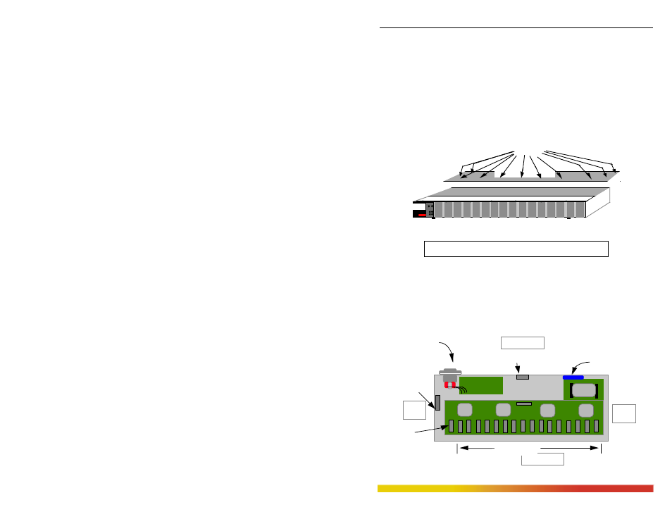
Step 1.
Remove Chassis Cover
To make the installation of port module easy, the top cover is made in two
parts called “front-top” and “rear-top”. There are 6 screws located on front-
top of the unit and two screws each on the left and right edges. Remove these
screws. Once these are removed, the front-top cover is easily lifted off the
chassis base.
When the front-top cover has been removed, the front-interior is exposed.
Figure 3.9.1a: Removing Chassis Cover
Caution: Be careful not to disturb the power supply.
Looking down into the Magnum 8000X unit, notice that there are individual
PM connector sockets for each PM card position. There are 16 PM slots located on the
front of the unit and a bonus slot for an SPM in the rear of the unit. A total of seventeen
slots for seventeen Ethernet segment connections are available. The extreme left
header-position in front is used by the LED Status module. (See Figure 3.9.1b).
Figure 3.9.1b: Magnum 8000X, Top View with Chassis Cover
10100
PWR
BRD
ACT
COL
Magnum 8000X
Mixed Media Hub
GARRETT
1
Front-topChassis Cover
10 Phillips Head
Screws on Front-top
Front of Unit
Media Connector
with electronic
Inter-Repeater Bus
Power Input
Sixteen PM Slots
Back of Unit
Right
Side
Left
Side
SPM Bonus Slot
Cooling Fan
Power Supply Board
Bridge
LED Status Slot