Setup, Warning – Graco Inc. 237-296 User Manual
Page 5
308-425
5
Setup
General Information
NOTE: Reference numbers and letters in parentheses
in the text refer to the callouts in the figures and the
parts drawing.
NOTE: Always use Genuine Graco Parts and Acces-
sories, available from your Graco distributor. Refer to
the Product Data Sheet for the pump, Form No.
305–787. If you supply your own accessories, be sure
they are adequately sized and pressure rated for your
system.
Fig. 2 is only a guide for selecting and installing sys-
tem components and accessories. Contact your Graco
distributor for assistance in designing a system to suit
your particular needs.
Prepare the Operator
All persons who operate the equipment must be
trained in the safe, efficient operation of all system
components as well as the proper handling of all fluids.
All operators must thoroughly read all instruction
manuals, tags, and labels before operating the equip-
ment.
Prepare the Site
The pump requires 150 scfm (4.2 m#/min) of com-
pressed air while operating at 90 psi (6 bar, 0.6 MPa)
air pressure and 60 cycles per minute. Ensure that you
have an adequate compressed air supply.
Refer to Fig. 2. Bring a compressed air supply line (A)
from the air compressor to the pump location. Be sure
all air hoses (A) are properly sized and pressure-rated
for your system. Use only electrically conductive
hoses. The air hose should have a 3/4 npsm(m)
thread.
Install a bleed-type shutoff valve (B) in the air line to
isolate the air line components for servicing. Install an
air line moisture trap and drain valve (C) to help re-
move moisture from the compressed air supply.
Keep the site clear of any obstacles or debris that
could interfere with the operator’s movement.
Have a grounded, metal pail available for use when
flushing the system or draining the fluid filter.
Grounding
WARNING
FIRE AND EXPLOSION HAZARD
Before operating the pump, ground the
system as explained below. Also read
the section
FIRE OR EXPLOSION HAZ-
ARD on page 4.
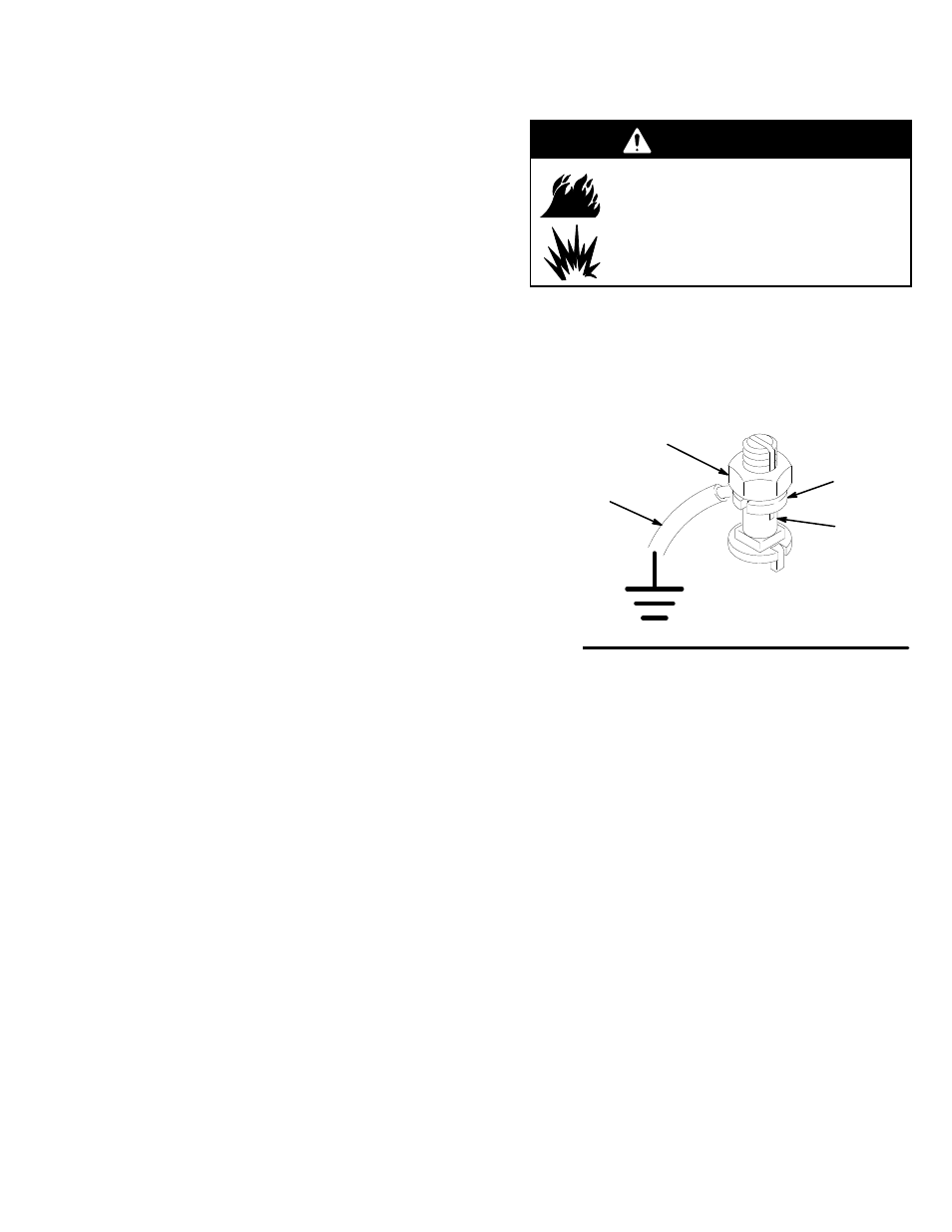
1.
Pump: use the ground wire and clamp (supplied).
See Fig. 1. Loosen the grounding lug locknut (W)
and washer (X). Insert one end of the ground wire
(26) into the slot in lug (Z) and tighten the locknut
securely. Connect the other end of the wire to a
true earth ground.
Fig. 1
W
X
26
Z
0864
2.
Air and fluid hoses: use only electrically conductive
hoses.
3.
Air compressor: follow manufacturer’s recommen-
dations.
4.
Spray gun: ground through connection to a prop-
erly grounded fluid hose and pump.
5.
Fluid supply container: follow your local code.
6.
Object being sprayed: follow your local code.
7.
Solvent pails used when flushing: follow your local
code. Use only metal pails, which are conductive,
placed on a grounded surface. Do not place the
pail on a nonconductive surface, such as paper or
cardboard, which interrupts the grounding continu-
ity.
8.
To maintain grounding continuity when flushing or
relieving pressure, hold a metal part of the spray
gun firmly to the side of a grounded
metal pail,
then trigger the gun.