Adjusting blade guide bearings – Grizzly Extreme Series Bandsaw G0514X User Manual
Page 35
G0514X/-X2/-X2B/-X3 (Mfg. Since 2/12)
-33-
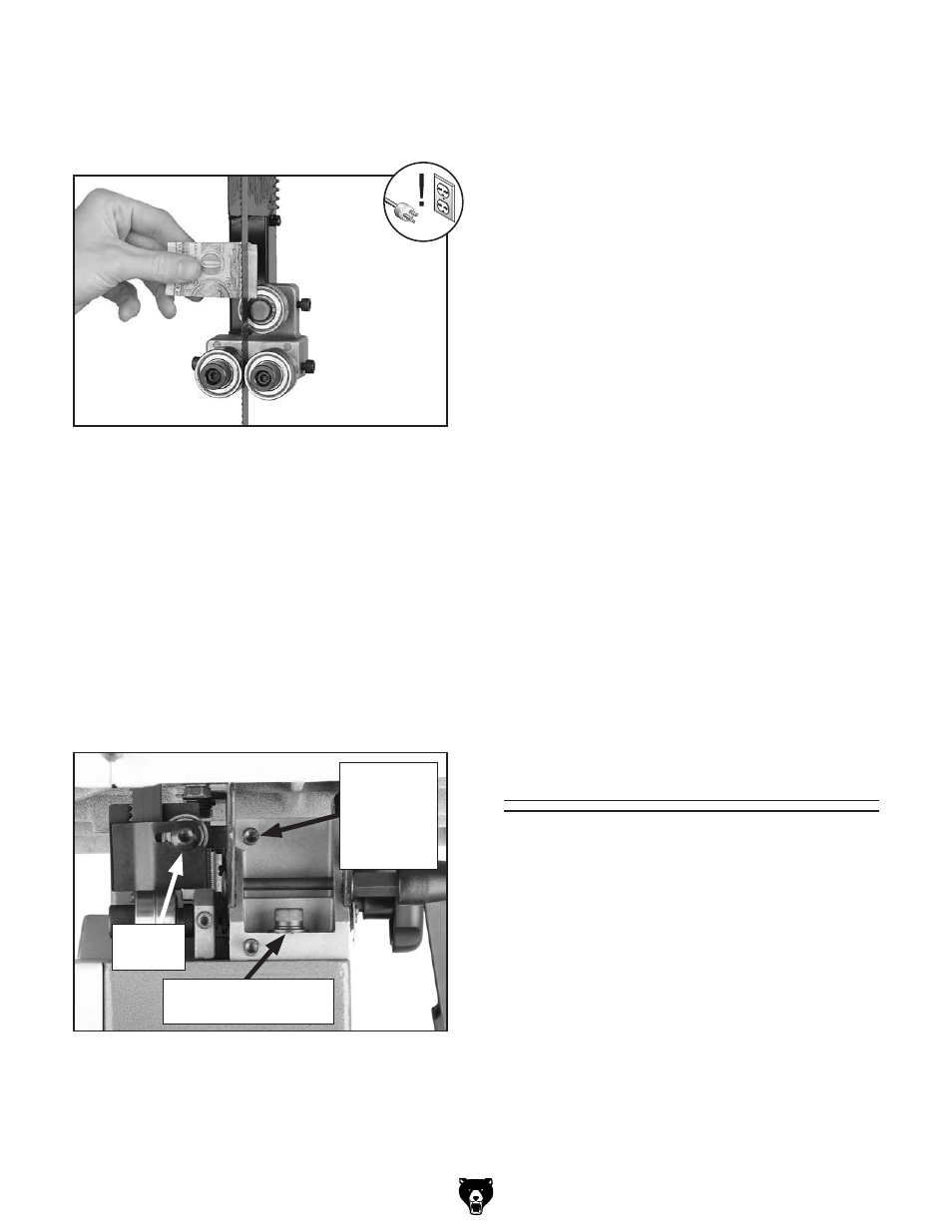
figure 53. dollar bill folded twice to make an
approximate 0.016" gauge.
Note: For a quick gauge, fold a dollar bill in half
twice (four thicknesses of a dollar bill is approxi-
mately 0.016") and place it between the support
bearing and the blade, as shown in
Figure 53.
8. tighten the cap screw to keep the support
bearing locked in place.
Adjusting Lower Support Bearings
1. disConneCt BandsaW FroM poWer!
2. Make sure that the blade is tracking properly
and is correctly tensioned.
3. Familiarize yourself with the lower support
bearing controls shown in
figure 54.
the blade guides provide side-to-side support to
help keep the blade straight while cutting. the
blade guides are designed to be adjusted in two
ways—forward/backward and side-to-side.
To adjust the upper and lower blade guides:
1. Make sure the blade is tracking properly and
that it is correctly tensioned.
2. disConneCt BandsaW FroM poWer!
Adjusting Blade
Guide Bearings
4. Check to make sure the guide block assem-
bly is perpendicular with the face of the sup-
port bearing as illustrated in
figure 51.
—if the guide block assembly is perpendicu-
lar to the face of the support bearing, con-
tinue on to the next step.
—if the guide block assembly is not per-
pendicular to the support bearing, loosen
the guide block assembly cap screws and
rotate the blade guide assembly side-to-
side until the blade is perpendicular with
the face of the support bearing, then re-
tighten the cap screws.
Note: The table
must be re-aligned with the blade after the
lower guide block assembly is adjusted.
Refer to
Page 35.
5. loosen the cap screw on the support bearing
adjustment shaft.
6. place a 0.016" feeler gauge between the
support bearing and the blade, and position
the bearing 0.016" away from the back of the
blade, as illustrated in
figure 52, or use a
dollar bill, as shown in
figure 53.
7. tighten the cap screw to keep the support
bearing locked in place.
figure 54. lower support bearing controls.
support
Bearing
adjustment
shaft Cap
screw
support
Bearing
guide Block
assembly Cap screw