Clearance reduction methods – Greenheck Fan Canopy Type Kitchen Hoods 452413 User Manual
Page 8
8
Kitchen Hoods • Type I and Type II
Clearance Reduction Methods
Clearance reduction methods have been evaluated and
tested and are listed by UL (Underwriters Laboratory).
The method of test was derived from the UL 710 test
standard.
The hood may be installed with zero clearance to
combustible materials if constructed in the following
manner.
1. One inch (2.54 cm) thick layer of insulation of Owens
Corning® Type 475, Johns Manville Type 475, IIG®
MinWool-1200® Flexible Batt, or Knauf Insulation
Type EI 475.
2. Insulation must be held securely in place. Pins that
are welded or secured with an adhesive may be
used.
3. A backsplash panel must be attached to the wall
(insulated or uninsulated).
To comply with the UL listing, the cooking appliances
must be as follows:
• Maximum surface temperature is 700°F (371°C)
• Appliances are located at least 3 in. (7.62 cm) from
the rear wall
• Appliances are at least 40 in. (101.6 cm) below the
bottom front edge of the hood
The hood may be installed with 3 in. (7.62 cm) clearance
to limited combustible materials per NFPA 96 if
constructed in one of the following methods:
• 3 in. (7.62 cm) rear uninsulated stand-off
• 3 in. (7.62 cm) top enclosure panel system
• 3 in. (7.62 cm) end uninsulated stand-off
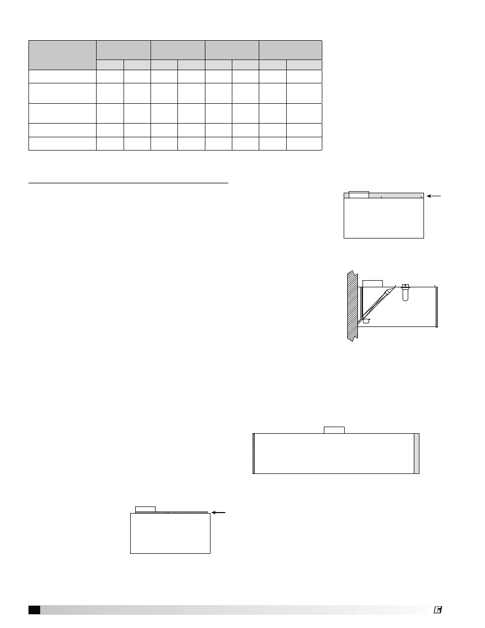
Top Clearance Reduction Options
One inch (2.54 cm) layer
of insulation installed
on top of the hood
(optional) meets zero
inch requirements for
clearance to combustible
surfaces as outlined under
the clearance reductions methods.
Three inches (7.62 cm)
insulated airspace
installed on top of hood
(optional) meets NFPA 96
requirements for clearance
to limited combustible
surfaces.
Back and Front Clearance Reduction Options
One inch (2.54 cm) layer
of insulation in 3 in. (7.62
cm) back stand-off meets
zero inch requirements for
clearance to combustible
surfaces as outlined under
the clearance reduction
methods.
Three inches (7.62 cm) uninsulated back stand-off
meets NFPA 96 requirements for clearance to limited
combustible surfaces.
One inch (2.54 cm) layer of insulation factory-installed
on the front of the hood (optional) meets zero inch
requirements for clearance to combustible surfaces.
End Clearance Reduction Options
One inch (2.54 cm) layer of insulation factory-installed
on the end of the hood (optional) meets zero inch
requirements for clearance to combustible surfaces
under the clearance reduction methods.
Three inches (7.62 cm) uninsulated airspace installed on
end of hood (optional). Meets NFPA 96 requirements for
clearance to limited combustible surfaces.
External Supply
Plenum Type
Weight
Width
Height
Length
per section
(lbs/ft)
(kg/m)
(in)
(mm)
(in)
(mm)
(ft)
(m)
Back Supply
35.0
52.09
6
152.4
Variable
Variable
3 to 16
.91 to 4.88
Air Curtain Supply
• 14 inch
9.5
14.14
14
355.6
10
254
3 to 16
.91 to 4.88
Air Curtain Supply
• 24 inch
12.5
18.60
24
609.6
10
254
3 to 16
.91 to 4.88
Variable Supply
16.0
23.81
12
304.8
18
457.20
3 to 16
.91 to 4.88
Horizontal Supply
14.0
20.83
12
304.8
18
457.20
3 to 16
.91 to 4.88
Weights and Dimensions
®