Electrical connections, Ductwork, Caution – Greenheck Fan Canopy Type Kitchen Hoods 452413 User Manual
Page 6: Double island style hoods, Installing u-channel strip, Continuous capture plenum hoods
6
Kitchen Hoods • Type I and Type II
Electrical Connections
Access for wiring the hood control panel (when
applicable) is provided by a junction box located on top
of the hood when the control panel is mounted in the
hood, or by the switch junction box when the control
panel is mounted in the fire protection cabinet. The
box is labeled “Control Voltage Wiring to Roof Top Fan
Package”. Use minimum 14 AWG copper wire. After
all the wiring is completed, install the light bulbs (light
bulbs not provided; standard light bulbs up to 100 watt
may be used).
Standard Greenheck light switches shipped on hoods
are rated for 15 amps and shall not have more than
14 lights connected to them. Higher amperage switches
are available upon special request.
Ductwork
Exhaust
As specified in NFPA 96, Ch. 7.5 (latest edition), exhaust
duct systems must be constructed in the following
manner:
Materials: Ducts shall be constructed of and supported
by carbon steel not less than 1.37 mm (0.054 in.) (No.
16 MSG) in thickness, or stainless steel not less than
1.09 mm (0.043 in.) (No. 18 MSG) in thickness.
Installation: All seams, joints, penetrations, and duct to
hood collar connections shall have a liquid-tight external
weld. If you have an automatic fire damper, please refer
to that manual for installation instructions now.
Supply
Supply ductwork (where applicable) should be
connected to the hood in a manner approved by the
local code authorities.
For proper installation of duct collars when they are
shipped unattached, see page 11.
CAUTION
For multiple hood systems that have more than 14
lights total (incandescent or fluorescent), the hood
lights must be wired to multiple circuits. Each circuit
must have less than 14 lights total.
NOTE
For hoods with fire dampers in the exhaust and
supply duct collars, an access panel for cleaning and
inspection shall be provided in the duct. This panel
shall be as close to the hood as possible but should
not exceed 18 in. (45.72 cm).
Double Island Style Hoods
A double island hood is created by installing two
wall style hoods back to back. Use the installation
procedure described on page 4 for single island hoods;
install and level both hoods. After leveling, secure the
hoods together by tack-welding and/or bolting the rear
mounting brackets together.
Installing U-Channel Strip
1. After the hood
is hung in
position and
leveled, apply
caulk to the
inside edge
of the double
island clip.
2. Position and
install the clip
by tapping
into position along clip (friction fit).
3. Caulk edges to seal out grease and allow for ease
of cleaning. Caulk with NSF Approved silicone caulk
(GE SCS1009 or its equivalent). The caulk is not
provided.
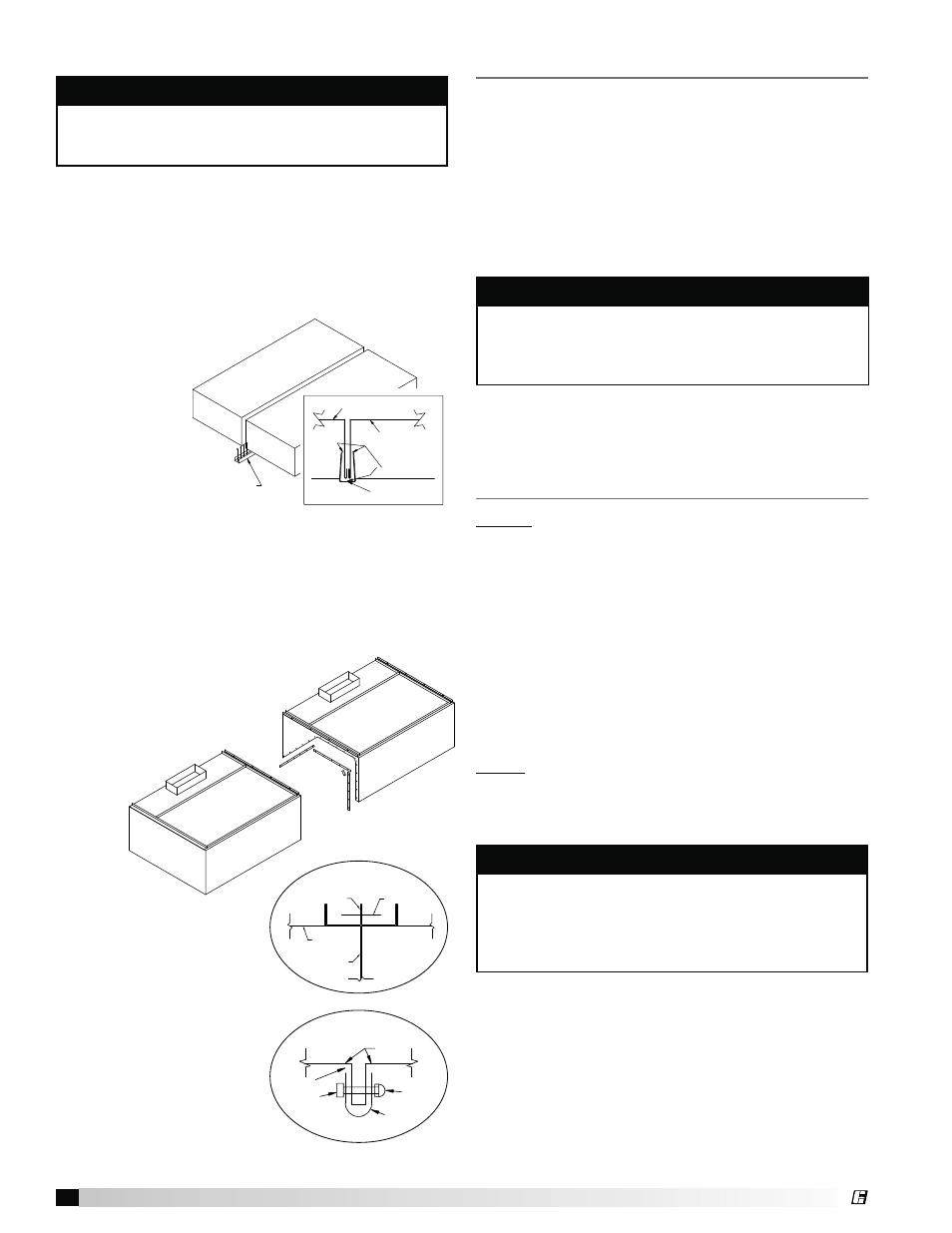
Continuous Capture Plenum Hoods
Remove the support angles provided
for support during shipping on
the open end panels. Use the
installation procedure
described on page 4
for single island
hoods;
install
and level
both
hoods.
After
leveling, secure
the hoods together by tack-
welding and/or bolting the
angles that are located at
the top of the hoods along
its width (Fig. 4).
Next, fasten the hoods
together at its inside plenum
profile using u-clips and
bolts (Fig. 5). Caulk this joint
with NSF Approved silicone
caulk (GE SCS1009 or its
equivalent). The caulk is not
provided.
After the hood is installed, remove all protective plastic.
NOTE
Before hanging the hoods, please verify the hood
marks to make sure the correct hood is hung on the
correct side.
HOOD FRONT
ITEM-1B
DOUBLE ISLAND CLIP
ITEM-1A
HOOD-1B
DOUBLE ISLAND CLIP
SILICONE CAULK
(GE SCS1009)
HOOD-1A
Fig. 4
BOLT OR WELD
HOOD TOP
HOOD END
SUPPORT ANGLES
CAULK
BOLT
U-CLIP
HOOD
ACORN
NUT
Fig. 5
2. RAISE
AND SU
3. FASTE
4. FASTE
5. CAULK
& CAP
1. REMO
HOOD FRONT
HOOD FRONT
REMOVE
SUPPORT
ANGLES ON
THE OPEN
END PANEL
®