Installing duct collars, Exhaust air balancing baffles (eabb), Back view of the hood – Greenheck Fan Canopy Type Kitchen Hoods 452413 User Manual
Page 11: Top view of the hood
11
Kitchen Hoods • Type I and Type II
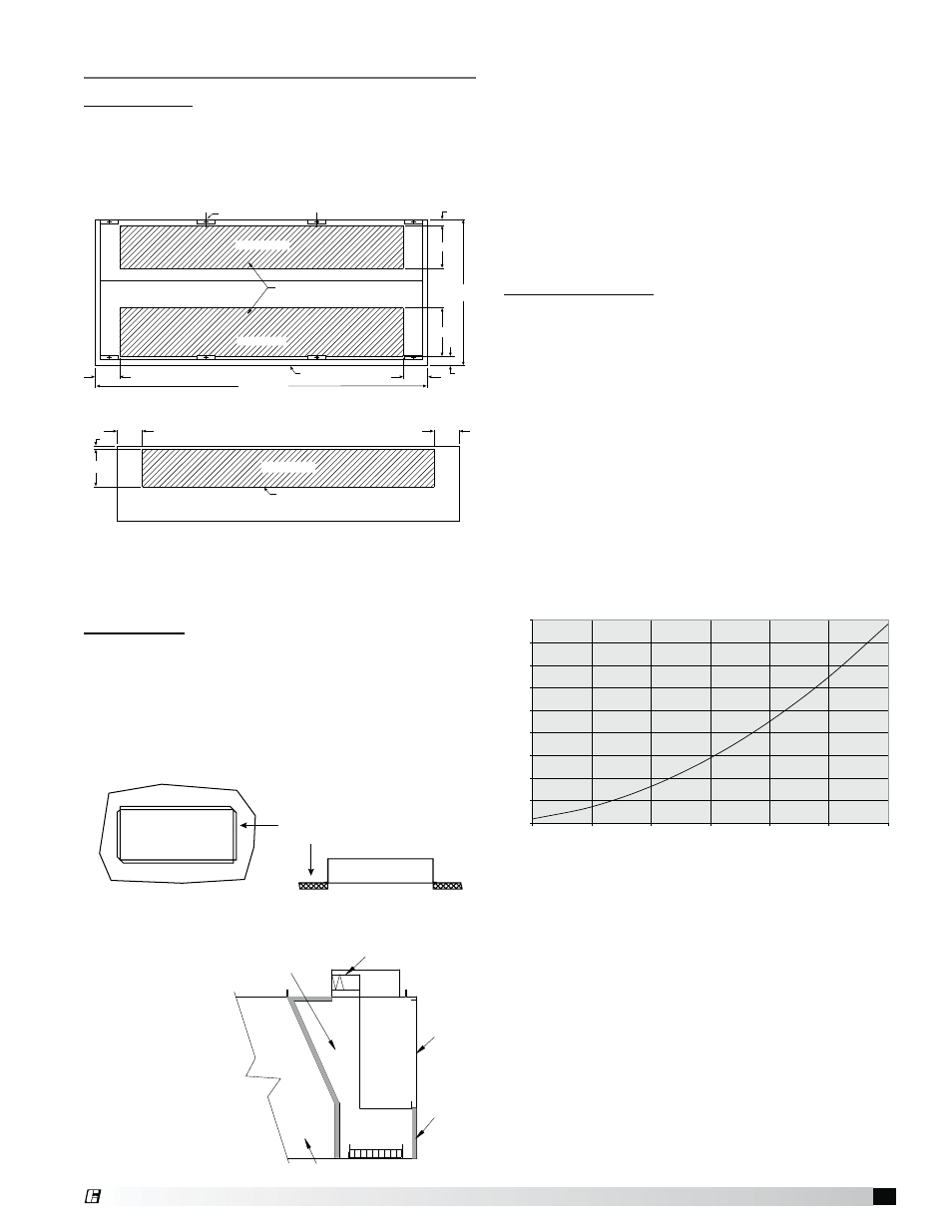
Duct cut out area
Hood Top
Exhaust Plenum
8 in.
8 in.
1 in.
12 in.
Back View of the Hood
Hanger Bracket
Exhaust Plenum
Duct cut out area
Supply Plenum
Hood Length
Hood
Width
Front of hood
8 in.
3 in.
3 in.
16 in.
14 in.
8 in.
Top View of the Hood
Maximum Increase in Static Pressure for Exhaust Air Balancing Baffle
(Fully Closed)
0
0.5
1
1.5
2
2.5
3
3.5
4
4.5
500
1000
1500
2000
2500
3000
3500
Duct Velocity FPM
In
cr
ease i
n
Co
ll
a
r St
ai
tc
Pr
essur
e
Installing Duct Collars
Exhaust Collars
1. The exhaust duct connection needs to be located
within 48 in. (121.92 cm) from the center of the hood
length to the center of the duct connection and within
shaded area as shown.
2. The exhaust duct connection is to be a continuous
liquid-tight weld. Weld with a non-ferrous filler wire,
such as silicon bronze or stainless steel filler wire.
Protect all stainless steel areas from weld splatter.
Supply Collars
1. The supply duct connection needs to be located
within the shaded Supply Plenum area as in the
drawing above.
2. The supply duct connection is tack-welded at 1 to
2 inch (2.54 to 5.08 cm) intervals or sheet metal
screws at 3 to 6 in. (7.62 to 15.24 cm) spacing to
the hood.
3. For hoods that are insulated, the edges of the
insulation must be taped after the hole is cut. (The
insulation tape
is provided by
others).
4. On combination
hoods, make
certain the
fire damper
is located
over the
internal supply
chamber.
Supply Duct
Connection
Supply duct connection to be tack
welded with 1 to 2 inch tack or
sheet metal screws at 3 to 6 inch
spacing to hood.
Internal Supply
Chamber
Supply Fire Damper
Insulated
Supply
Plenum
Exhaust Capture
Hood
Exhaust Air Balancing Baffles (EABB)
This is a guide to assist in determining if multiple
hoods on one fan can be balanced to have equal static
pressure. For multiple hoods on one fan to achieve their
designed exhaust flow, all of the hoods must have equal
static pressure at their designed exhaust flow.
The laws of physics force the static pressure for each
branch of a duct system on one fan to always be equal.
This will happen by the flow rate increasing in low static
branches and decreasing in high static branches until
the static pressure is equal in all branches.
Checking for Balance
Every hood with exhaust air balancing baffles (EABB)
has a range for its static pressure. The low static
pressure number (when EABB is open) in this range is
given by the standard calculation for hood static and is
printed on the CAPS submittal page for that hood. The
high static pressure number (when EABB is closed) in
this range can be found by calculating the maximum
potential increase of static and adding that value to the
low static pressure number.
High static pressure number = low static pressure
number + maximum increase
The maximum potential increase in static is given in the
graph, or can be calculated from the following formula:
Maximum Increase = 0.00000036 x (Duct velocity)
2
®