Ductwork connections, Supply weatherhood, Exhaust weatherhood – Greenheck Fan HEAT RECOVERY UNIT WITH EVAPORATIVE COOLING HRE-20 User Manual
Page 5: Dampers, Rail mounting, Supply weatherhood will be factory mounted
5
1 Fan
Wheel
Dia.
1 Fan
Wheel
Dia.
Rot
atio
n
Rot
atio
n
R
ot
ation
R
ot
ation
Length of Straight Duct
GOOD
POOR
GOOD
POOR
GOOD
POOR
Turning
Vanes
Turning
Vanes
SYSTEM EFFECT FACTOR CURVES
FPM X 100
OUTLET VELOCITY
0 5 10 15 20 25 30 35 40 45
1.2
1.0
0.8
0.6
0.4
0.2
0.0
S
TA
TIC PRESSURE LOSS
CUR
VE
1
CUR
VE
2
CUR
VE
3
CUR
VE 4
1 Fan
Wheel
Dia.
1 Fan
Wheel
Dia.
Rot
atio
n
Rot
atio
n
R
ot
ation
R
ot
ation
Length of Straight Duct
GOOD
POOR
GOOD
POOR
GOOD
POOR
Turning
Vanes
Turning
Vanes
SYSTEM EFFECT FACTOR CURVES
FPM X 100
OUTLET VELOCITY
0 5 10 15 20 25 30 35 40 45
1.2
1.0
0.8
0.6
0.4
0.2
0.0
S
TA
TIC PRESSURE LOSS
CUR
VE
1
CUR
VE
2
CUR
VE
3
CUR
VE 4
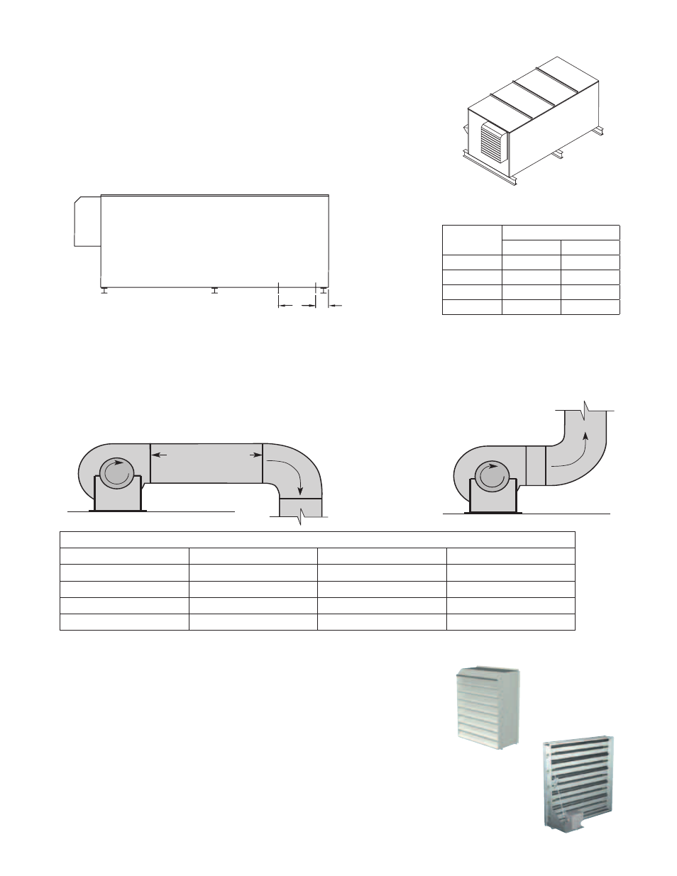
DUCTWORK CONNECTIONS
Examples of good and poor fan-to-duct connections are shown below . Airflow out of the fan should be directed
straight or curve the same direction as the fan wheel rotates . Poor duct installation will result in low airflow and
other system effects .
Rail Layout
• Rails designed to handle the weight of the HRE should be
positioned as shown on the diagram (rails by others) .
• Make sure that rail positioning does not interfere with the supply
air discharge opening or the exhaust air intake opening on the
HRE unit . Avoid area dimensioned “B” below
• Rails should run the width of the unit and extend beyond the unit
a minimum of 12 inches on each side .
• Set unit on rails.
A
B
SUPPLY/EXHAUST
OPENING
OUTDOOR
AIR
INTAKE
HOOD
A
B
SUPPLY/EXHAUST
OPENING
OUTDOOR
AIR
INTAKE
HOOD
Isometric view of HRE on rails
Side view of HRE on rails
Dimensions shown are in inches .
SUPPLY WEATHERHOOD
Supply weatherhood will be factory mounted .
EXHAUST WEATHERHOOD
The exhaust weatherhood is shipped separately as a kit with its own
instructions .
DAMPERS
Backdraft dampers are always included as an integral part of the
exhaust hood assemblies . Motorized outdoor air and exhaust air
dampers are optional and are factory mounted (and wired) at the
inlet .
RAIL MOUNTING
Recommended Discharge Duct Size and Length
HRE Model
HRE Blower Size
Duct Size
Straight Duct Length
HRE-20
10
14 x 14
40
HRE-45
12
20 x 20
48
HRE-55
15
28 x 28
60
HRE-90
18
32 x 32
72
Model
Rail Mounting
A
B
HRE-20
5 .1
25 .0
HRE-45
7 .1
25 .1
HRE-55
5 .7
35 .0
HRE-90
6 .6
36 .1
All dimensions shown are in inches .