Hre water supply connection location – Greenheck Fan HEAT RECOVERY UNIT WITH EVAPORATIVE COOLING HRE-20 User Manual
Page 11
11
7 . Verify that both airflow and system static pressure are in agreement with the specifications . If these
conditions are met, check for water carry over from the discharge side of the media . If carry over is
observed, check the distribution header for holes or tears and the water standoff tube for blockage .
8 . After all final adjustments are made, remove the jumper wires, connect “call for cooling” signal, and replace
all access panels . The unit is now ready for operation .
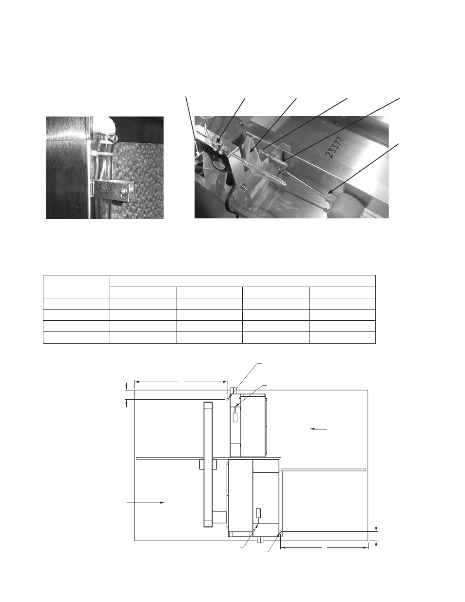
Bleed-Off
Valve
Overflow
Pump
Filter
Threaded
Float
Adjustment
Supply
Connection
Float
Valve
Pump and Float Components
HRE WATER SUPPLY CONNECTION LOCATION
B
A
Ø 0.875
Run 1/4 inch line up through 7/8 inch
hole here and bring around end
of sump to supply connection.
D
C
Ø 0.875
Run 1/4 inch line up through 7/8 inch
hole here and bring around end
of sump to supply connection.
OA INLET
EA INLET
1/4 inch Water Supply Connection
1/4 inch Water Supply Connection
Model
Water Supply Connection Locations
A
B
C
D
HRE-20
37 .375
4 .625
4 .625
39 .25
HRE-45
38 .75
4 .625
4 .625
43 .00
HRE-55
43 .50
4 .625
4 .625
46 .125
HRE-90
43 .50
4 .625
4 .625
52 .625
Dimensions from outside of unit (in inches)
Top View
Water Flow Adjustment Device