Installation, Lifting, Unit weights & recommended roof opening – Greenheck Fan HEAT RECOVERY UNIT WITH EVAPORATIVE COOLING HRE-20 User Manual
Page 3: Safety warning
3
INSTALLATION
The system design and installation should follow
accepted industry practice, such as described in the
ASHRAE Handbook .
Adequate space should be left around the unit for piping
coils and drains, filter replacement, and maintenance .
Sufficient space should be provided on the side of the
unit for routine service and component removal should
that become necessary .
See Service Clearances/Access Panel Locations section
for more details .
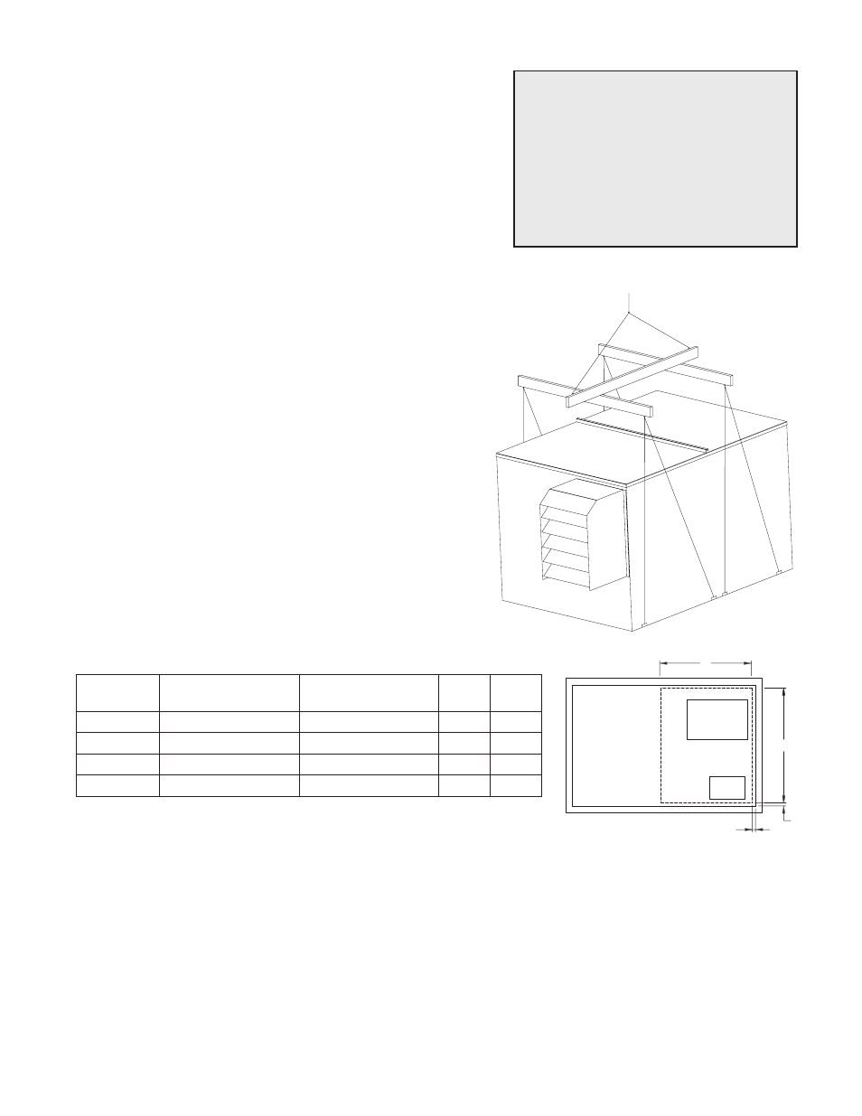
LIFTING
1) Before lifting, be sure that all shipping material has
been removed from unit .
2) To assist in determining rigging requirements,
weights are shown below .
3) Unit must be lifted by the eight lifting lugs provided
on base structure .
4) Rigger to use suitable mating hardware to attach to
unit lifting lugs .
5) Spreader bar(s) must span the unit to prevent
damage to the cabinet by the lift cables .
6) Always test-lift the unit to check for proper balance
and rigging before hoisting to desired location .
7) Never lift units by weatherhoods.
8) Never lift units in windy conditions.
9) Preparation of curb and roof openings should be
completed prior to lifting unit to the roof .
10) Check to be sure that gasketing (supplied by others)
has been applied to the curb prior to lifting the unit
and setting on curb .
11) Do not use fork lifts for handling unit .
Lift using
lifting lugs and
spreader bar
UNIT WEIGHTS & RECOMMENDED ROOF OPENING
SUPPLY
OUTLET
EXHAUST
INLET
U
V
0.50
0.50
Unit Size
Approx. Dry Weight
(lbs)
Approx. Wet Weight
(lbs)
U
V
HRE-20
1660
1800
46
37
HRE-45
2580
2840
54
39
HRE-55
2950
3320
65
47
HRE-90
4750
5400
85
49
SAFETY WARNING
All factory provided lifting lugs must
be used when lifting the units . Failure
to comply with this safety precaution
could result in property damage,
serious injury, or death .
Unit weights assume indirect evap, direct evap, and IG furnace .
All dimensions shown are in inches .
Position the unit roof opening such that the supply discharge and exhaust inlet of the unit will line up with the
corresponding ductwork . Be sure to allow for the recommended service clearances when positioning opening
(see Service Clearances) . Do not face the outdoor air inlet of the unit into prevailing wind and keep the supply
inlet of the unit away from any other exhaust fans . Likewise, position the exhaust discharge opening away from
fresh air intakes of any other equipment .
When cutting only duct openings, cut opening 1 inch (25mm) larger than duct size to allow clearance for
installation . Area enclosed by roof curb must comply with clearance to combustible materials . If the roof is
constructed of combustible materials, area within the roof curb must be ventilated, left open, or covered with
non-combustible material which has an ÒRÓ value of at least 5 . If area within curb is open, higher radiated
sound levels may result .
Where the supply or warm air duct passes thru a combustible roof, a clearance of one inch must be maintained
between the outside edges of the duct and combustible material in accordance with NFPA Standard 90A.