Installation, Install anti-tip device (continued), Step 3 – GE Monogram ZDP48N6D User Manual
Page 10
Concrete or Cement Construction:
Hardware Required (not supplied):
[2] sleeve anchors, lag bolts and washers.
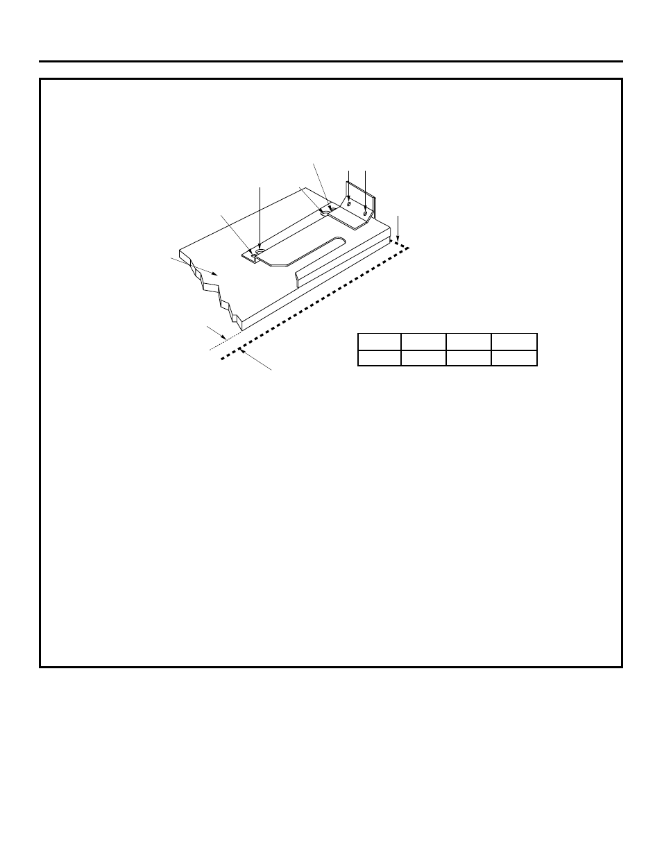
• Place the bracket against the back wall, into the
right rear corner of the installation location.
• See Dimension A, position the bracket the correct
distance from the right side. Mark the 2 large holes
for fastening the bracket to the floor and remove
the bracket.
• Drill recommended size holes for the hardware.
• Install the sleeve anchors into the holes and then
install the lag bolts through the bracket. The bolts
must be properly tightened as recommended for
the hardware.
• Fasten the bracket securely to the floor.
• Drive wood screws into the back wall.
Dimension A
A=
1/2"
5/8"
1/4"
Models
ZDP48
ZDP36
ZDP30
Back
Wall
(2) Wood Screws into
Back Wall
(All Installations)
Small Hole For Wood
Installations (2 Total)
(2) Large Holes For
Concrete Installations
Small Holes For Wood
Installations (2 Total)
Wood
Slide
Strip
Dimension A
Righ
t Sid
e Of
Wall o
r Ran
ge
10
INSTALL ANTI-TIP DEVICE
(CONTINUED)
Wood Construction:
• Place the bracket against the back wall, into the right
rear corner of the installation location.
• See Dimension A, position the bracket the correct
distance from the right side. Mark the 2 small screw
holes for fastening the bracket to the floor and remove
the bracket.
• Drill two, 1/8" diameter pilot holes.
• Fasten the bracket securely to the floor and wall using
all 4 screws provided.
STEP 3
Installation