Installation instructions, Installation – vented to the outside, Step 1, install framing for hood support – GE Monogram ZV755 User Manual
Page 9: Important, Install framing for hood support, Ductwork, wiring locations
9
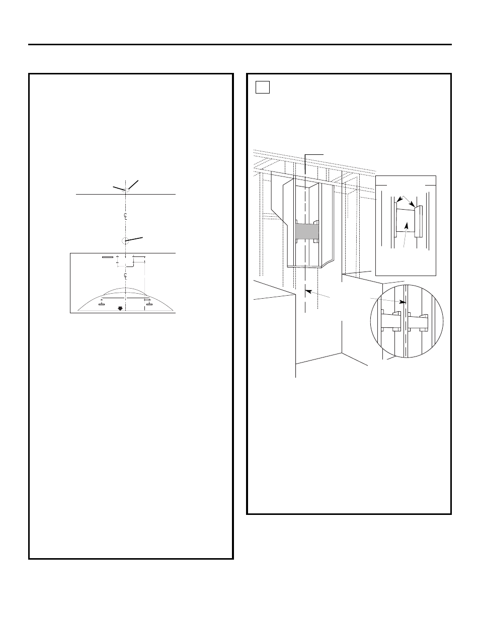
INSTALL FRAMING FOR
HOOD SUPPORT
IMPORTANT
—
The vent hood must be
secured to rear support framing or a wall stud.
Framing must be capable of supporting 100 lbs.
If drywall is present, mark the screw hole locations
for the top mounting brackets. Remove the template.
• Cut away enough drywall to expose 2 vertical studs
at the bracket location indicated on the template.
• Install a horizontal support at least 1″ x 12″
between two wall studs at the mounting screw
location. The horizontal support must be flush with
the room side of the studs. Use cleats behind both
sides of the support to secure to wall studs.
IMPORTANT: Reinstall drywall for an even mounting
surface.
1
Installation Instructions
View from
rear cleats
1″ x 12″ min.
mounting
support
DUCTWORK, WIRING LOCATIONS
Determine the exact location of the vent hood.
• Locate the template packed with the literature.
– Measure 36″ from the floor to the top of the
cooking surface. Add hood installation height
determined on page 8. Mark that location.
– Use a level to draw a straight pencil line on the wall.
– Tape the template in position along the penciled
line. CHECK TO BE SURE THE TEMPLATE IS LEVEL.
Ceiling ducting:
If ductwork will vent straight up to the ceiling:
• Use a level to draw a line straight up, from
the centerline on the template to the ceiling.
• Measure 3-3/4″ from the back wall to the centerline
of an 6-1/2″ hole on the ceiling.
NOTE: If drywall is not present, add drywall thickness
to the 3-3/4″ dimension.
Wall Ducting:
If ductwork will vent to the rear:
• Use a level to draw a line straight up from the
centerline on the template.
• Measure at least 6″ above the bracket location shown
on the template to the centerline of a 6-1/2″-dia. duct
hole. (Hole may be elongated for duct elbow.)
HOUSE WIRING LOCATION:
• The junction box is located on the top left side
of the hood.
• Wiring can enter from the back wall or ceiling above
the top bracket location. Route additional wiring
length to reach the junction box.
INSTALLATION – VENTED TO THE OUTSIDE
6-1/2″ min. opening for ductwork
• Drill 1/8" Pilot Holes For Mounting Brackets.
Align edge 25-1/2" above Cooking Surface.
17-5/16"
3-15/16"
13-9/16"
2-5/32"
C
L
• Drill 1/8" Pilot Holes.
• Drill 1/8" Pilot Holes.
5-7/8"
FOR WALL
VENT DUCT
Centerline 6″ min. above
bracket location
FOR CEILING VENT DUCTING
3-3/4″ c enterline to wall
Centerline of
installation
space
NOTE: 2 horizontal supports
will be needed if there is a
stud located between the
horizontal screw locations.