4 performance monitor pm-50 – Furuno FR-2135S User Manual
Page 58
4-14
10.Fasten the front panel of the display pedestal.
11.Fasten the ground wire to the location shown in Figure 4-14.
12.Close the monitor.
4.4 Performance Monitor PM-50
Necessary parts: PM-50 and OP03-150 (Code no. 008-485-490)
e
m
a
N
e
p
y
T
y
t
Q
.
o
N
e
d
o
C
d
r
a
o
B
M
P
5
2
2
9
P
3
0
1
w
e
r
c
S
d
a
e
H
n
a
P
W
0
0
7
2
C
8
x
3
M
3
4
0
4
-
1
8
8
-
0
0
0
.
y
s
s
A
r
o
t
c
e
n
n
o
C
A
A
-
0
0
3
L
-
P
3
H
V
2
4
1
0
-
1
4
1
-
0
0
0
1. Lift the monitor. See Chapter 1 for instructions.
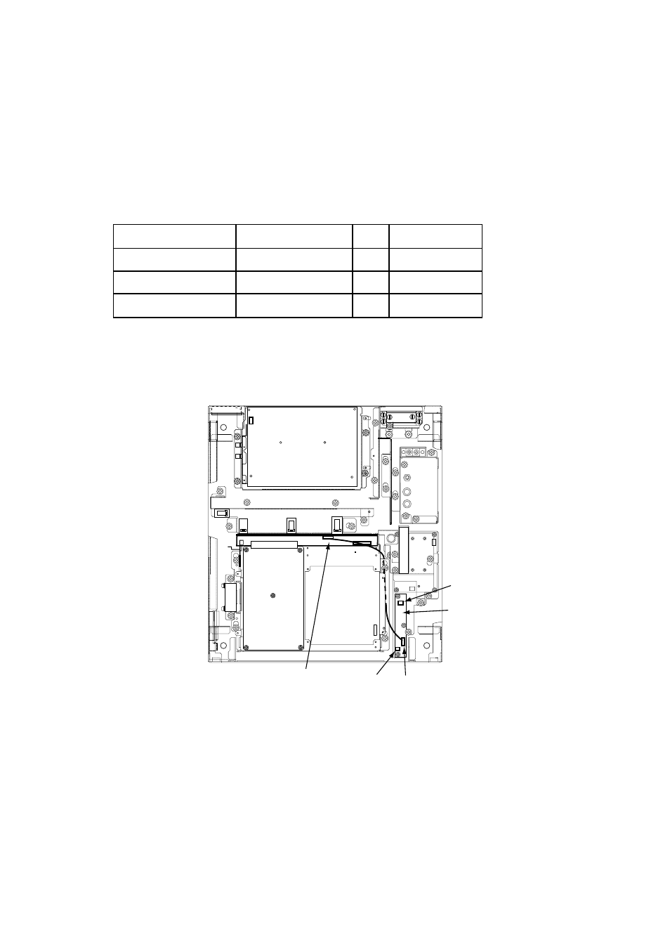
2. Fasten the PM Board 03P9225 to the location shown below with three screws
(M3 x 8).
J401
J411
PM Board
03P9225
J403
J402
Figure 4-15 Display unit, inside view
3. Connect the connector P401 coming from J411 to J401 on the PM Board.
4. Connect two connector assemblies (VH3P-L300-AA) to J402 and J403.
5. Solder the other end of there connector assemblies with external cables, one
from ship’s mains and one from the PM-30.
6. Peel off the seal located to the right of the antenna switch in the tuning com-
partment on the control head to access PM switch. (Refer to page 1-14 for
location.)
7. Close the monitor.