Furuno FR-2135S User Manual
Page 46
4-2
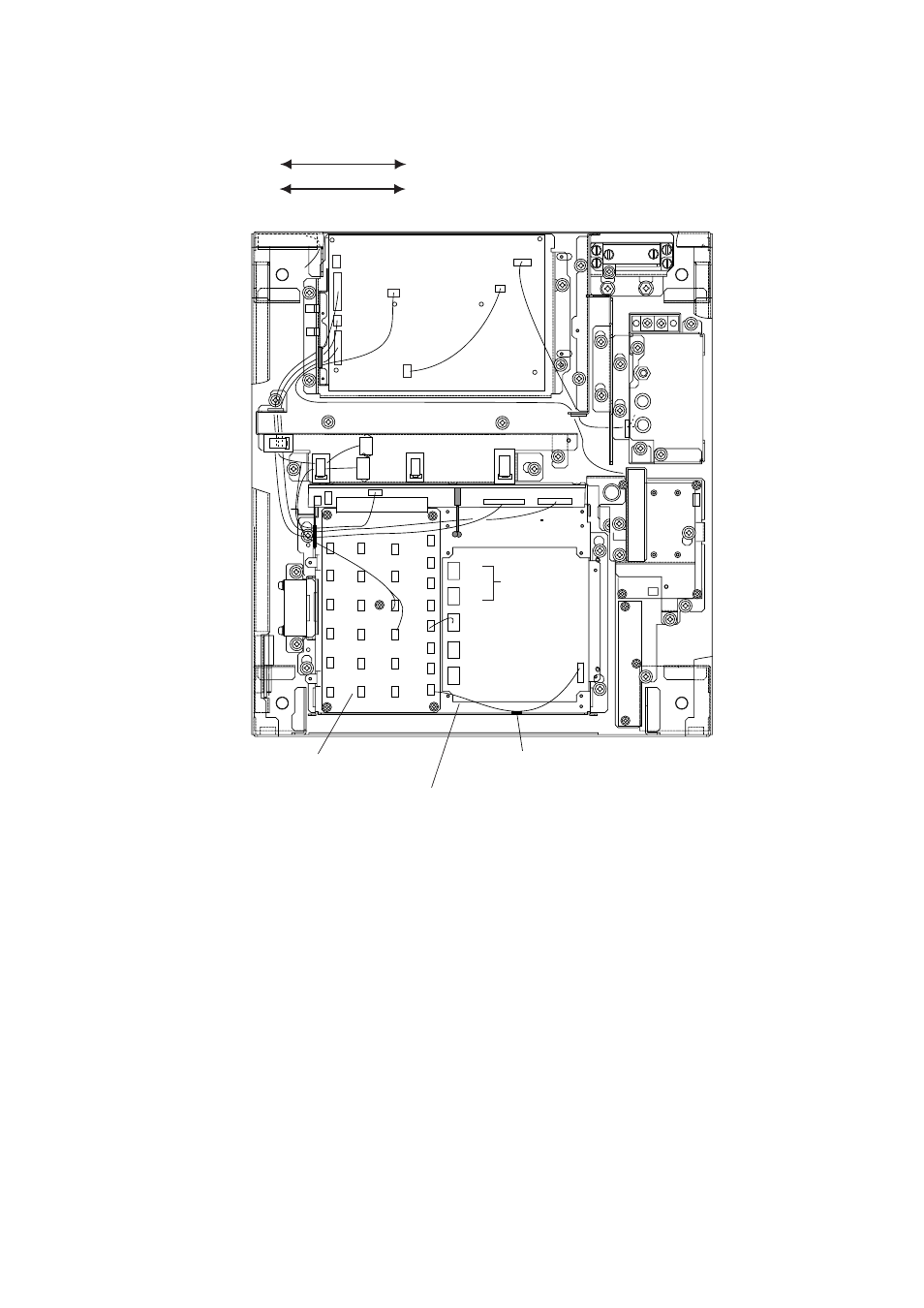
4) Connect the GYRO CONVERTER Board to the INT Board (cables supplied
with GC-8) as shown below.
INT Board GYRO CONVERTER Board
J446 (4P)
J7 (5P)
J465 (6P)
J1 (14P)
INT BOARD
03P9252
GYRO CONVERTER
BOARD 64P1106
J1
J5
J4
To gyro
J7
Fix cable to chassis
with cable tie.
J446
Figure 4-2 Display unit, inside view
5) Confirm gyrocompass specifications and set up the DIP switches and jumper
wires on the GYRO CONVERTER Board according to gyrocompass connected:
• Setting jumper wires and DIP switches by gyrocompass
specifications: page 4-3
• Setting jumper wires and DIP switches by make and
model of gyrocompass: page 4-5
• Location of jumper wires and DIP switches: page 4-6
6) Solder the gyrocompass cable to the VH connector assemblies (supplied).
7) Attach instruction label (supplied).
8) Close the display unit.
9) Turn the power off and on to reset the CPU.
- 2817-D (136 pages)
- 841 MARK-2 (58 pages)
- FAR-2157-BB (111 pages)
- UAIS TRANSPONDER FA-150 (4 pages)
- NAVNET 1763C (260 pages)
- FR-1710 (78 pages)
- FAR-2807 (52 pages)
- MARINERADAR FR-8062 (56 pages)
- 1935 (48 pages)
- FR-7062 (52 pages)
- FR-7252 (48 pages)
- COLOR VIDEO PLOTTER 1943C (251 pages)
- NAVPILOT 520 (73 pages)
- FAR-2167DS (111 pages)
- NAVpilot NAVpilot-500 (73 pages)
- FAR-2827 (135 pages)
- NAVNET 1823C (260 pages)
- FR-2155 (89 pages)
- FA-100 (58 pages)
- NAVNET 1943 (248 pages)
- 1622 (24 pages)
- FR-2115/2125 (79 pages)
- 1942 MARK-2 (52 pages)
- 1942 MARK-2 (46 pages)
- 2137S (123 pages)
- 1832 (62 pages)
- 1832 (64 pages)
- 1832 (63 pages)
- FAR-2167DS-D (111 pages)
- 821 (64 pages)
- FR-8251 (69 pages)
- FAR-2127-BB (136 pages)
- NX-700A/B (89 pages)
- MSC.36(63) (1 page)
- IF-1500AIS (12 pages)
- FR-8051 (64 pages)
- FAR-2157 (111 pages)
- FAR-2157 (8 pages)
- 1712 (27 pages)
- UAIS TRANPONDER FA-150 (128 pages)
- FAR-2107(-BB) (312 pages)
- NATVET 1824C (239 pages)
- FAR-2107 (280 pages)
- NAVPILOT 500 (73 pages)