Display unit modification procedure – Furuno FR-2135S User Manual
Page 19
1-11
Separate type control head kit (Type: OP03-151, No.: 008-485-530)
e
m
a
N
e
p
y
T
y
t
Q
.
o
n
e
d
o
C
s
k
r
a
m
e
R
.
y
s
s
A
e
l
b
a
C
P
1
/
P
0
2
B
S
6
4
2
L
U
1
2
1
8
-
0
4
1
-
0
0
0
2
2
4
9
S
3
0
,
m
0
1
t
e
e
F
r
e
b
b
u
R
3
0
0
5
-
J
S
4
7
8
7
-
1
0
8
-
0
0
0
e
p
a
t
/
w
r
e
v
o
C
t
n
o
r
F
r
o
t
i
n
o
M
1
6
3
1
-
5
5
2
-
3
0
1
0
4
3
-
3
6
2
-
0
0
1
e
t
a
l
P
g
n
i
x
i
F
B
K
1
9
6
1
-
4
4
1
-
3
0
1
0
4
9
-
3
6
2
-
0
0
1
e
t
a
l
P
e
l
d
n
a
H
2
3
6
1
-
4
4
1
-
3
0
1
1
4
0
-
8
6
2
-
0
0
1
B
K
r
e
v
o
c
t
s
u
D
3
9
6
1
-
4
4
1
-
3
0
1
0
6
7
-
1
7
2
-
0
0
1
w
e
r
c
S
0
1
x
4
M
3
6
4
4
-
1
8
8
-
0
0
0
l
e
b
a
L
1
1
0
1
-
3
0
0
-
6
8
1
0
3
2
-
6
3
2
-
0
0
1
r
e
b
b
u
R
p
i
h
s
n
o
N
4
9
6
1
-
4
4
1
-
3
0
1
0
6
7
-
1
7
2
-
0
0
1
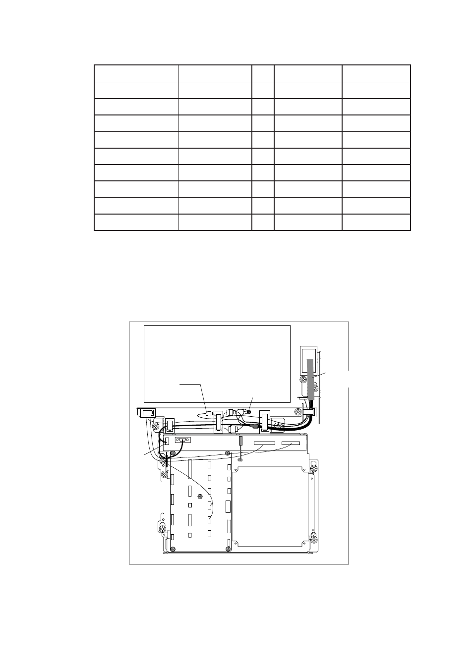
Display unit modification procedure
1. Raise the monitor unit referring to procedure for tabletop mounting on page 1-
8.
2. Unplug two connectors from the control head cable (P412 from MOTHER Board
and J583 and unfasten two earth wires.
MB 03P9251
INT
03P9252
J583
P412
J418
Earth Wire
PTU COVER
Control Head
Cable
Figure 1-13 Display unit, inside view
3. Lower the monitor.
- 2817-D (136 pages)
- 841 MARK-2 (58 pages)
- FAR-2157-BB (111 pages)
- UAIS TRANSPONDER FA-150 (4 pages)
- NAVNET 1763C (260 pages)
- FR-1710 (78 pages)
- FAR-2807 (52 pages)
- MARINERADAR FR-8062 (56 pages)
- 1935 (48 pages)
- FR-7062 (52 pages)
- FR-7252 (48 pages)
- COLOR VIDEO PLOTTER 1943C (251 pages)
- NAVPILOT 520 (73 pages)
- FAR-2167DS (111 pages)
- NAVpilot NAVpilot-500 (73 pages)
- FAR-2827 (135 pages)
- NAVNET 1823C (260 pages)
- FR-2155 (89 pages)
- FA-100 (58 pages)
- NAVNET 1943 (248 pages)
- 1622 (24 pages)
- FR-2115/2125 (79 pages)
- 1942 MARK-2 (52 pages)
- 1942 MARK-2 (46 pages)
- 2137S (123 pages)
- 1832 (62 pages)
- 1832 (64 pages)
- 1832 (63 pages)
- FAR-2167DS-D (111 pages)
- 821 (64 pages)
- FR-8251 (69 pages)
- FAR-2127-BB (136 pages)
- NX-700A/B (89 pages)
- MSC.36(63) (1 page)
- IF-1500AIS (12 pages)
- FR-8051 (64 pages)
- FAR-2157 (111 pages)
- FAR-2157 (8 pages)
- 1712 (27 pages)
- UAIS TRANPONDER FA-150 (128 pages)
- FAR-2107(-BB) (312 pages)
- NATVET 1824C (239 pages)
- FAR-2107 (280 pages)
- NAVPILOT 500 (73 pages)