FUJITSU MHW2060AC User Manual
Page 130
Interface
•
Command data structure
Indicates the command received when an error occurs.
•
Error data structure
Indicates the status register when an error occurs.
•
Total number of drive errors
Indicates total number of errors registered in the error log.
•
Check sum
Two's complementary for the lowest-order 1 byte that is obtained by adding 1 byte
after another for as many as 511 bytes beginning from the top of the structure.
•
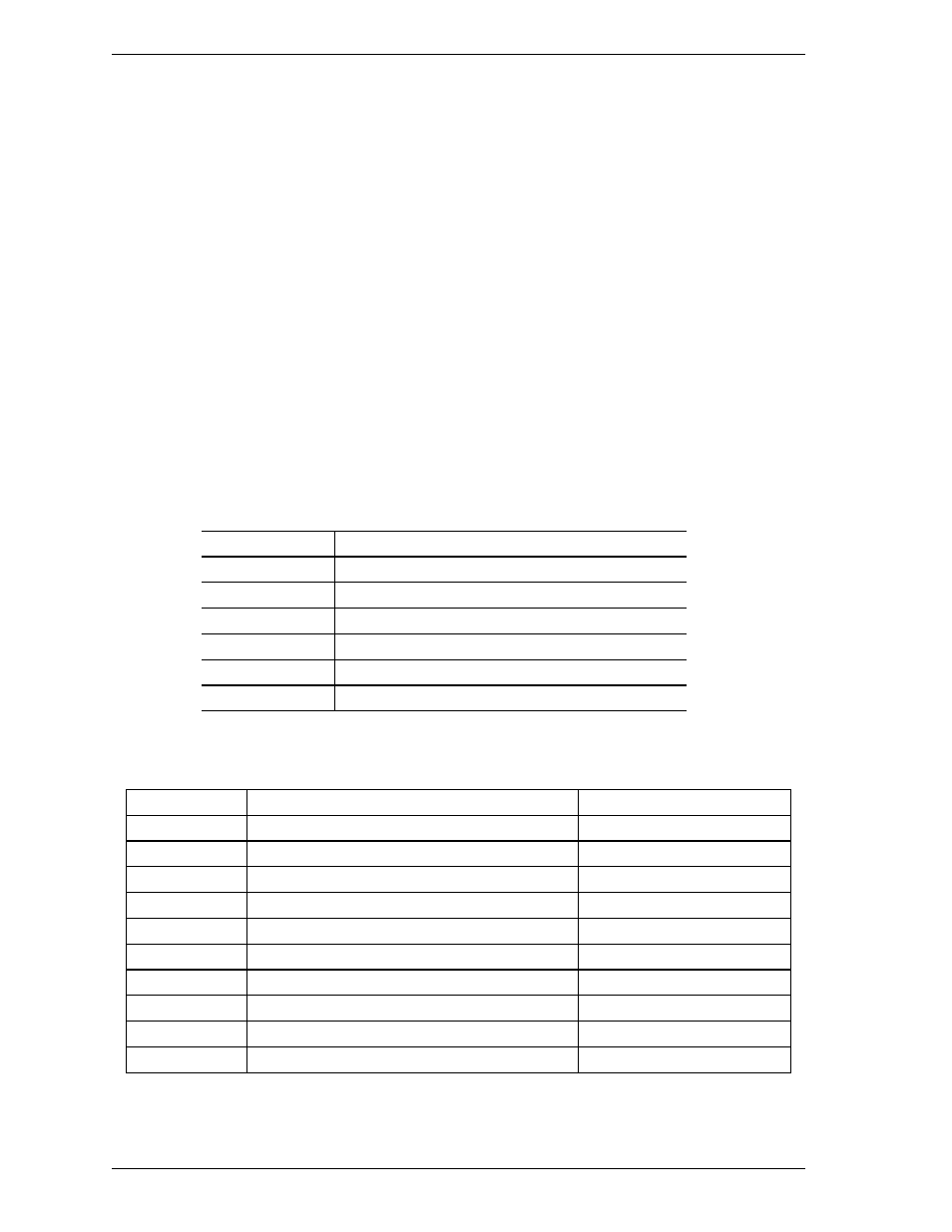
Status
Bits 0 to 3: Indicates the drive status when received error commands according to
the following table.
Bits 4 to 7: Vendor unique
Status Meaning
0 Unclear
status
1 Sleep
status
2 Standby
status
3
Active status (BSY bit = 0)
4
Off-line data collection being executed
5 to F
Reserved
Table 5.17 Data format of SMART Comprehensive Error Log
Byte
First sector
Next sector
00h
SMART Error Logging 01h
Reserved
01h
Index Pointer Latest Error Data Structure.
Reserved
02h...5Bh 1
st
Error Log Data Structure
Data Structure 5n + 1
5Ch...B5h 2
nd
Error Log Data Structure
Data Structure 5n + 2
B6h...10Fh 3
rd
Error Log Data Structure
Data Structure 5n + 3
110h...169h 4
th
Error Log Data Structure
Data Structure 5n + 4
16Ah...1C3h 5
th
Error Log Data Structure
Data Structure 5n + 5
1C4h...1C5h
Total Error Count
Reserved
1C6h...1FEh Reserved
Reserved
1FFh Checksum
Checksum
5-54
C141-E258