3 external signal input/output, Caution, 3 external signal input/ output – Furuno FMD-8010 User Manual
Page 41
3 – 3
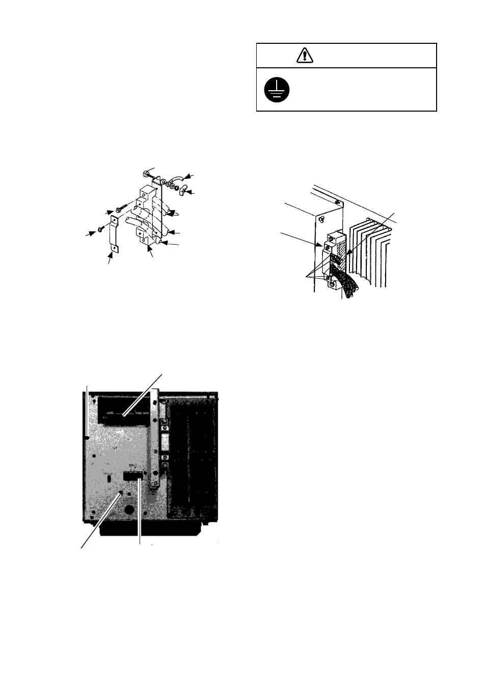
1) Remove the display unit cover.
2) Dismount the clamping plate from the cable
clamp by loosening two screws.
3) Lay the signal cable and power cable in-
side the cable clamp. Fasten the clamping
plate to the cable clamp by using two M4
x
12 screws. If optional equipment are con-
nected, secure the clamping plate by using
two M6
x
30 bolts.
Figure 3-5 Laying cables in the cable clamp
4) Connect the power cable and signal cable
by referring to the interconnection diagram.
Fasten shields of those cables to chassis.
Figure 3-6 Display unit, rear view
5) Run a ground wire (IV-8 sq, or equivalent)
from the ground terminal to nearest ground
point.
Screw
Ground
wire
Wing nut
Cables of
optional equipment
Signal cable
Power cable
Cable clamp
Clamping
plate
M4 x 12
M6 x 30
It is recommended to seal the cable gland
(with aluminum tape, etc.) to keep foreign
objects out of the display unit.
Figure 3-7 Sealing the cable gland
3.3 External Signal Input/
Output
Input from external equipment
As shown in Figure 3-8, this radar accepts
inputs from a wide variety of equipment. All
external equipment are connected to the SPU
Board, which is near the DJ connector at the
rear of the display unit. Use XH connector
assy. to connect external equipment.
FURUNO can provide a signal cable assem-
bly; 5m, 2-pair cable with XH-5 connector at-
tached.
Cover cable
gland with
aluminum
tape, etc.
Cable
clamp
Cables
(power,
signal,etc.)
DTB-1
#1(+), #2(-)
Fasten shield of
power cable here.
Fasten shield of
signal cable here.
Connect DJ1
and J201 here.
CAUTION
Ground the equipment to prevent
electrical shock and mutual
interference.