12 the heading and north markers, 13 measuring the range – Furuno FMD-8010 User Manual
Page 22
1 – 12
1.12 The Heading and North
Markers
The heading marker indicates the ship's heading
in all presentation modes. It appears at zero de-
grees on the bearing scale in the Head-up mode,
in any direction depending on the ship orienta-
tion in North-up and True Motion modes. The
north marker appears as a short dashed line. In
the Head-up mode, the north marker moves
around the bearing scale in accordance with the
compass signal.
To temporarily extinguish the heading marker to
look at targets existing dead ahead of own ship,
press the HM OFF (PUSH) control. The heading
marker reappears when the key is released.
1.13 Measuring the Range
There are three ways to measure the range to a
target: by the range rings, by the cursor and by
the VRM (Variable Range Marker).
Measuring range by the range rings
Use the range rings to obtain a rough estimate of
the range to a target. They are concentric circles
around own ship, or the sweep origin. The num-
ber of rings is automatically determined by the
selected range scale and their interval is displayed
at the upper-left position of the screen. Press the
RINGS (PUSH) control to show the range rings
if they are not displayed. Successive presses of
the RINGS (PUSH) control gradually increase
the brightness of the rings in four steps and a fifth
press erases the rings.
Measuring range by the cursor
Rotate the trackball to place the cursor on the in-
side edge of the target. The range to the cursor
appears at the bottom of the display.
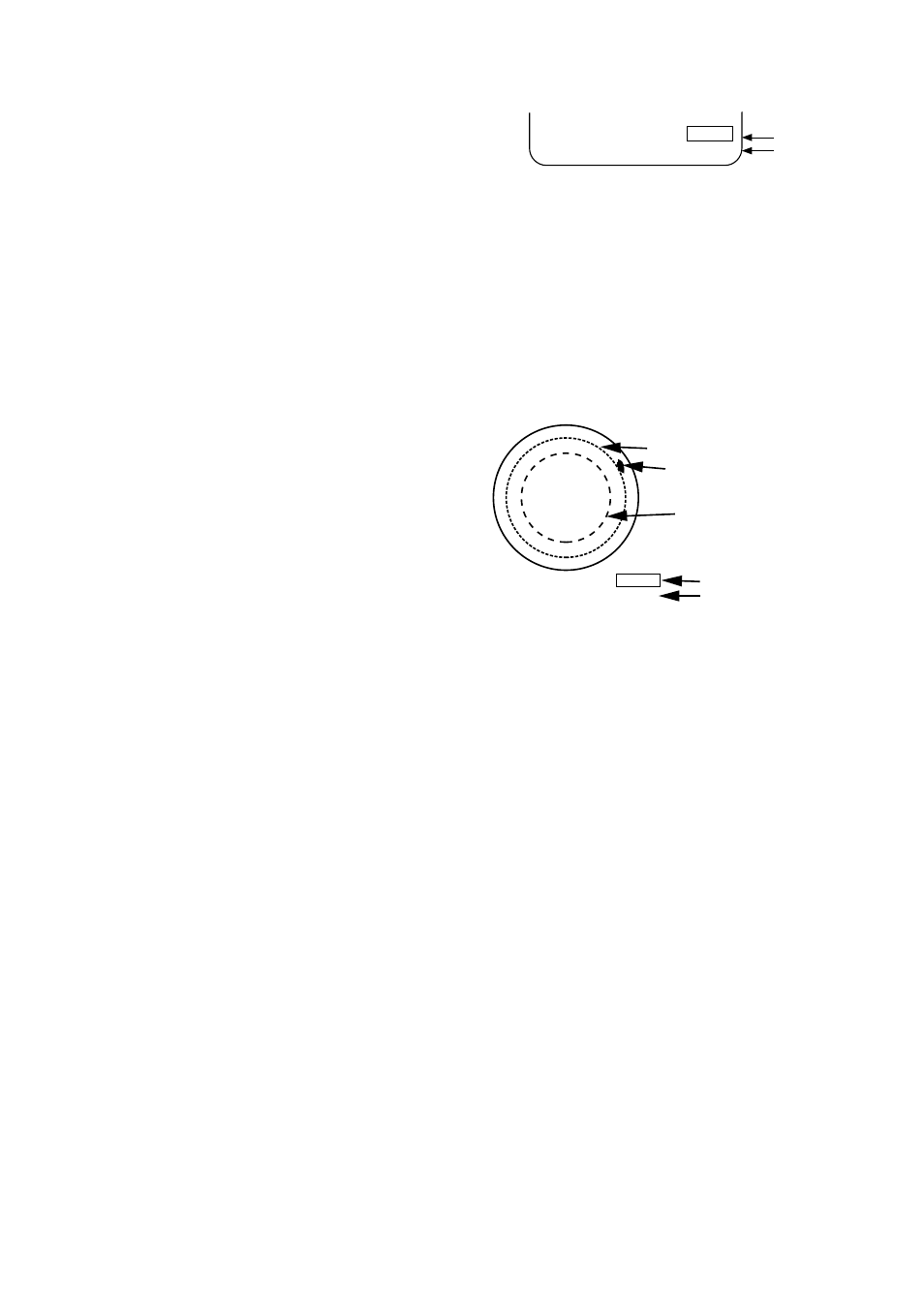
Measuring range by VRM
1) Press the VRM ON key to enable a VRM. Each
pressing of the key enables the No.1 VRM or
No.2 VRM alternately. The active marker’s
readout is circumscribed.
5.03nm
12.5nm
No.1 VRM
No.2 VRM
VRM
Figure 1-10 Location of VRM readouts
2) Operate the VRM control to place the outside
edge of the VRM on the inside edge of the
target.
3) Check the VRM readout at the bottom right
corner of the display to find the range to the
target.
No.1 VRM
No.2 VRM
5.0nm
4.0nm
No.1 VRM range
No.2 VRM range
Target
6.0NM
1.0
VRM
Figure 1-11 How to measure range by VRM
Erasing VRMs
1) If two VRMs are displayed, press the VRM
ON key to circumscribe the VRM readout of
the VRM you want to keep active.
2) Press the VRM OFF key. The VRM readout
and its associated VRM are erased.
Note:
You can select unit of range measurement
for the cursor and VRM on the INITIAL menu.
For further details see 1.35 Selecting Unit of
Range Measurement, Bearing Reference.