Connecting the cables, Ethernet wiring requirement for poe, Power wiring – Pelco IME3ICM-E In-Ceiling Mount for Sarix Enhanced 3 Series Cameras User Manual
Page 19: Ethernet wiring requirement for poe+ power wiring
C6644M (2/20)
19
Connecting the Cables
If previously removed, reinstall the camera module by screwing it into the backbox.
The I/O interfaces will be seen on the front of the camera module. Make the appropriate cable connections.
ETHERNET WIRING REQUIREMENT FOR POE+
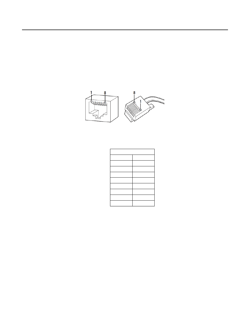
Connect a Cast5e cable or higher cable (not supplied) to the RJ-45 network connector. the 8-pin port includes video over Ethernet, and PoE+ for
the camera. PoE+ injects power over the same cabling that carries the network data, eliminating the need for a separate power supply. This
simplifies the installation and operation of the camera without affecting network performance.
Figure 10.
Pin Numbering
Figure 11.
Pin Functions
POWER WIRING
To wire the connector, insert cables into the power connector (supplied). Attach the cables per Figure 1 (e.g. Pin 1 is 12 VDC or 24 VAC 1; Pin 2 is
GND or 24 VAC 2) with a small slotted screwdriver and then plug the adapter plug into the camera.
NOTE:
12 VDC OR 24 VAC may be used instead of PoE+ or in addition to PoE+ for power failover in case PoE+/network is temporarily lost.
1000BASE-TX
Pin
Function
1
BI_DA+
2
BI_DA-
3
BI_DB+
4
BI_DC+
5
BI_DC-
6
BI_DB-
7
BI_DD+
8
BI_DD-