Product overview – Pelco IME3ICM-E In-Ceiling Mount for Sarix Enhanced 3 Series Cameras User Manual
Page 11
11
C6644M (2/20)
Product Overview
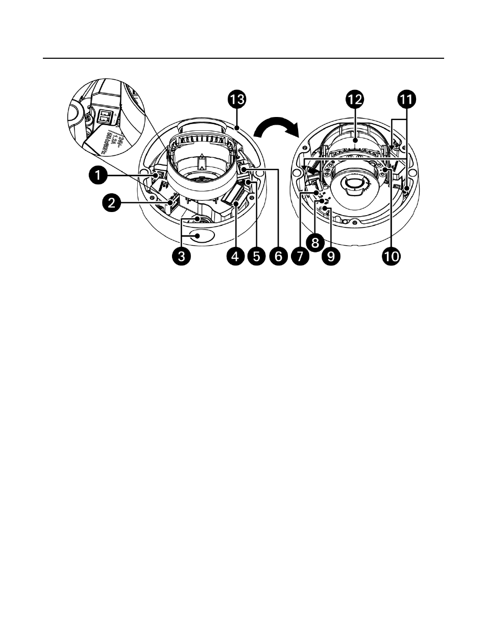
Figure 1.
Sarix Enhanced IME Series Dome Camera
1.
Power Connector:
A two-pin connector for 12 VDC or 24 VAC.
2.
RJ-45 Network Port:
Connects the camera to the IP network. also supplies power to the camera (POE+), through the same connector. (Note: To
purchase a power supply, please contact Pelco for further information.)
a.
Green LED:
With solid green, the LED indicates a live connection is established.
b.
Orange LED:
With flashing orange, the LED indicates data is being transmitted/received between camera and switch.
3.
NPT 3/4”-14:
Gland/conduit connection. It is recommended to use conduit when possible for cable entry into the housing. The Sarix IME Series
camera comes with two conduit openings (side and top entry). Only one entry is intended to be used. The other entry must be blocked with the
conduit plug (supplied).
4.
Alarm/Relay/Audio Port:
Connects to alarms, relays, and audio in/out.
5.
Connector:
Not used.
6.
Micro SD Card Slot:
Install the SD card into the card slot to store videos and snapshots. Do not remove the micro SD card when the camera is
powered on.
a.
To install the micro SD card, the dome cover must be taken off from the camera.
7.
Reset Button:
Cycles power to the camera and initiates a reset. Press and release the reset button once to reboot the camera.
8.
Defaults Button:
Press and hold the button for 4 seconds to restore the camera to factory default settings.
9.
Microphone:
Microphone for capturing sound.
10.
Status LED Indicator
:
a.
Solid red for more than 5 seconds indicates there is a booting error. Flashing green indicates booting is normal.
b.
Flashing orange indicates a firmware update is in progress.
c.
LED will turn off after a successful boot up.
d.
Solid Amber indicates the camera is in a cold start state (warming up before fully booting).
11.
Camera Module Screws:
Three screws used to attach the camera module to the back box. Camera module can be removed during installation to
make it easier to install the product and protect the camera during the installation process (optional).
12.
Camera Module:
The physical main body of the camera.
13.
Backbox:
Bottom camera cover enclosure.
14.
Lower Dome:
Top camera cover enclosure. (Not shown)